Heavy-duty machinery often requires high starting torque, smooth low-speed rotation and reliable operation under changing loads. In hydraulic systems, radial piston motors are designed to meet these demanding requirements, often allowing machinery to operate with little or no additional speed reduction. They are used in selected winch, wheel-drive, mining and industrial applications where compact, high-torque hydraulic motors of this type offer practical advantages over alternative drive arrangements.
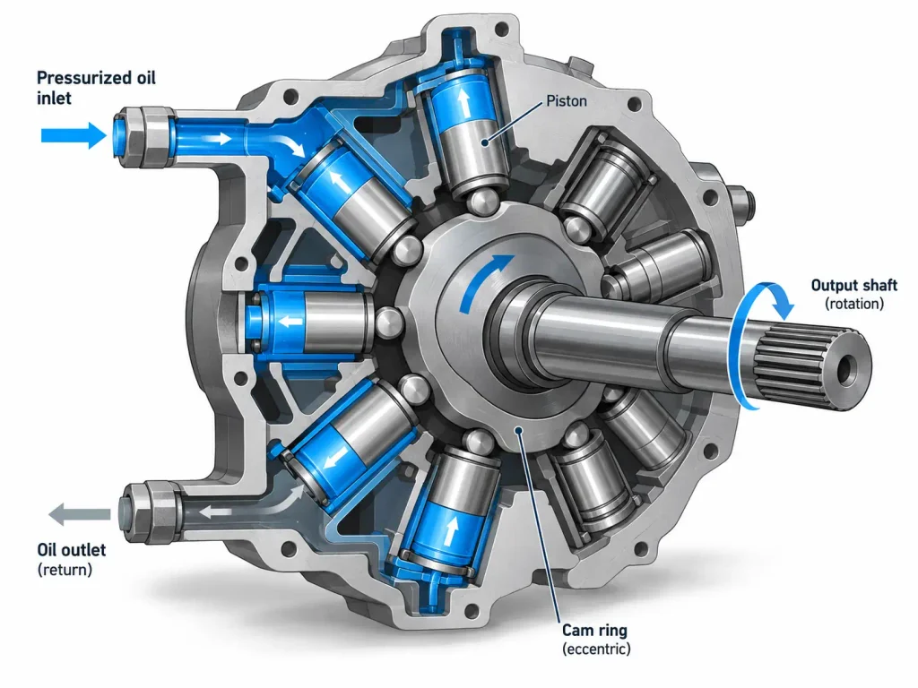
A radial piston motor converts hydraulic pressure and flow into rotary torque by arranging a set of pistons radially around the output shaft. Pressurised oil drives each piston through its working stroke, and an eccentric mechanism or a cam profile converts the piston force into a tangential driving force that rotates the shaft. A distribution mechanism admits and discharges oil in step with shaft rotation, so torque is produced continuously rather than in a single stroke.
Understanding why the layout behaves this way begins with what separates a radial arrangement from other piston designs, and then with the components and the force path that turn reciprocating motion into steady rotation.
What Is a Radial Piston Motor?
A radial piston motor is a rotary hydraulic actuator in which the pistons are arranged radially in a cylinder block, perpendicular to the centreline of the output shaft, so that hydraulic pressure and flow are converted into torque and angular displacement. Because a large total piston area can be pressurised while the shaft turns slowly, radial designs are a strong option for low-speed, high-torque applications.
A hydraulic motor is any rotary actuator that converts hydraulic pressure and flow into torque and angular displacement, the counterpart of a cylinder that produces linear force and stroke. The radial piston type sits at the high-torque end of that family, delivering high torque at relatively low rotational speeds, so it can often drive a load directly without a gearbox. Its defining feature is the piston orientation: each piston reciprocates along a radius, so its line of motion is perpendicular to the shaft axis.
Radial Piston Motor vs Axial Piston Motor
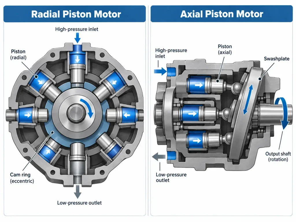
Both are piston machines, but the geometry changes the force path and the output character.
| Design aspect | Radial piston motor | Axial piston motor |
| Piston orientation | Radial to the cylinder block axis | Axial to the cylinder block axis; shaft alignment depends on design |
| Motion conversion | Eccentric or cam mechanism | Swashplate or bent-axis mechanism |
| Contact element | Roller or slipper against the eccentric or cam | Slipper against a swashplate, or rod against a flange |
| Piston side loading | Carried by the contact element and the housing | Carried by the slipper or the connecting rod |
| Output character | Very high torque at low speed | Higher speed with high power density |
| Displacement choice | Fixed, dual or variable, depending on the design | Fixed and continuously variable designs are both common |
In an axial piston motor, the pistons reciprocate along the cylinder block axis, which may be aligned with or inclined relative to the output shaft, and the angled swashplate or drive flange produces the tangential component that rotates the shaft. In a radial motor the pistons push outward from the centre, so a separate eccentric or cam geometry must convert that thrust into rotation. The two arrangements differ in package shape and in where the reaction forces are carried.
Radial Piston Motor vs Radial Piston Pump
The two devices share a radial architecture and are easy to assume interchangeable, but the energy conversion runs in opposite directions. A piston pump takes mechanical rotation and produces hydraulic flow; a motor takes flow and produces rotation. Port timing, lubrication, drain arrangement and bearings are optimised for the intended direction.
Some radial piston motors are explicitly rated for pump mode and can operate either way within published limits, but that cannot be assumed for the category. Before substituting one device for the other, the rated conditions, porting and timing, internal lubrication, case drain and mounting arrangement must be confirmed for that specific model.
Core Components of a Radial Piston Motor
The design is built from a small set of common components, plus one structure-specific assembly that determines how piston force becomes shaft torque.
The common components are:
- Housing and bearings, which contain the pressurised oil and carry the radial loads imposed by the pistons.
- Cylinder block, which holds the pistons in radial bores and carries the internal passages linking each chamber to the distribution mechanism.
- Pistons and contact elements, meaning the rollers or slippers fitted to the outer end of each piston to spread the contact load and support a lubricating film.
- Distribution mechanism, such as a pintle, valve plate or distributor, which routes high-pressure oil to the chambers entering their working phase and connects the rest to the return line.
- Output shaft, which transmits rotation to the driven machine.
The structure-specific assembly is either an eccentric shaft, sometimes described as a crankshaft, or a multi-lobe cam ring. These are alternative solutions to the same problem, and a given motor uses one or the other as its working conversion element.
Crankshaft Type vs Cam Ring Type
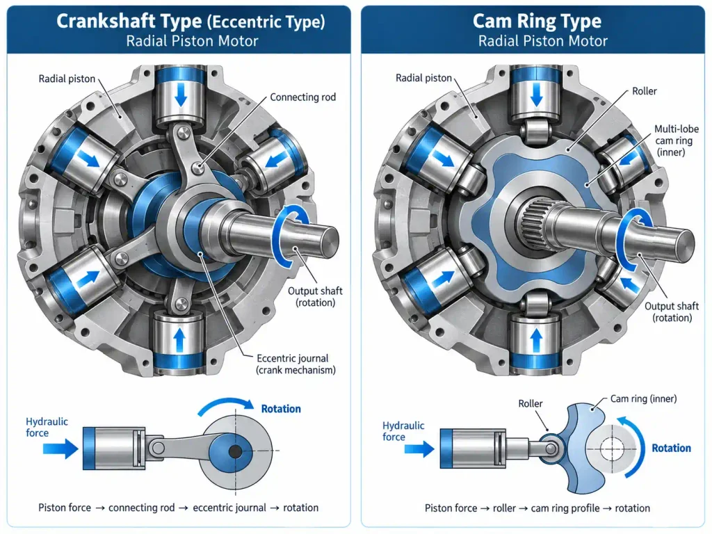
In the crankshaft or eccentric type, each piston acts through a connecting rod or contact element onto a journal whose centre is offset from the shaft centreline. Because the line of action does not pass through the rotation centre, the journal turns.
In the cam ring type, the pistons are held in a cylinder block while the cam ring provides the reaction surface. As pressure drives a piston outward, the roller on its end presses against the inner cam flank. With several lobes, the cam produces several working strokes per piston per revolution, raising displacement and smoothing the output.
| Feature | Crankshaft or eccentric type | Cam ring type |
| Force transmission | Piston acts through a rod or contact element onto an eccentric journal | Piston roller presses against the inner cam profile |
| Source of the torque arm | Eccentricity of the journal relative to the shaft centre | Slope of the cam flank relative to the rotation centre |
| Working strokes per revolution | Normally one per piston | One per cam lobe, so multi-lobe cams multiply the strokes |
| Practical character | Extremely high torque at very low speed | Large displacement with smooth output from multi-lobe geometry |
How Does a Radial Piston Motor Work? Step by Step
Hydraulic pressure drives the pistons, while the eccentric mechanism or cam profile converts piston force into a tangential driving force that generates shaft torque. Oil is admitted to the chambers entering their working phase and discharged from those leaving it, so the sequence repeats and the shaft keeps turning.
One full cycle consists of four repeating events:
- High-pressure oil enters the working chambers.
- Hydraulic pressure drives the pistons through their working strokes.
- The eccentric or cam mechanism converts piston motion into rotational torque.
- Oil leaves the low-pressure chambers as the cycle repeats.
From Fluid Pressure to Piston Force
Pressure applied to a confined fluid is transmitted undiminished throughout it, which is the principle known as Pascal’s law. Applied to a piston chamber, it gives the force acting on the piston face:
F = P × A
Here F is force in newtons, P is the pressure differential across the piston in pascals, and A is the piston area exposed to that pressure in square metres. Force therefore scales directly with area, so a large total working area produces very large force at modest pressure. Because the pistons act in different directions around a common centre, the geometry of the conversion element is what combines them into one useful output.
From Piston Force to Shaft Torque
The way piston force becomes torque differs between the two structures.
In the crankshaft or eccentric type, force is transmitted through a connecting rod or contact element to the eccentric journal. The journal centre is offset from the shaft centreline by the eccentricity, so the line of action passes at a distance from the rotation centre. That distance is the moment arm, and the product of force and moment arm is the torque that turns the shaft.
In the cam ring type, the piston and roller press against the inner flank of the cam. That flank is inclined relative to the direction of piston travel, so the reaction at the contact point resolves into a component along the piston axis and a component tangential to the direction of rotation. The tangential component is what drives the rotating element. The radial piston thrust on its own does not produce rotation; the inclination of the cam flank is what converts that thrust into a driving force.
A single piston produces torque over only part of a revolution, so the motor relies on several pistons being in different phases at any moment. The distribution mechanism is timed to the shaft position so that chambers switch from pressure to return as they finish their working stroke, keeping at least one piston productive at all times. That synchronisation makes the output continuous rather than a series of separate pushes, and a unit built around it is the essence of a low-speed high-torque radial piston hydraulic motor.
How smooth that output is depends on the number of pistons, the cam profile where one is used, the phase distribution and the porting design. Torque ripple is a function of those parameters together, and it is not determined by whether the piston count is odd or even. Some production families use an even number of radially arranged pistons and still achieve very smooth output through their cam and porting design.
Displacement, Torque and Speed
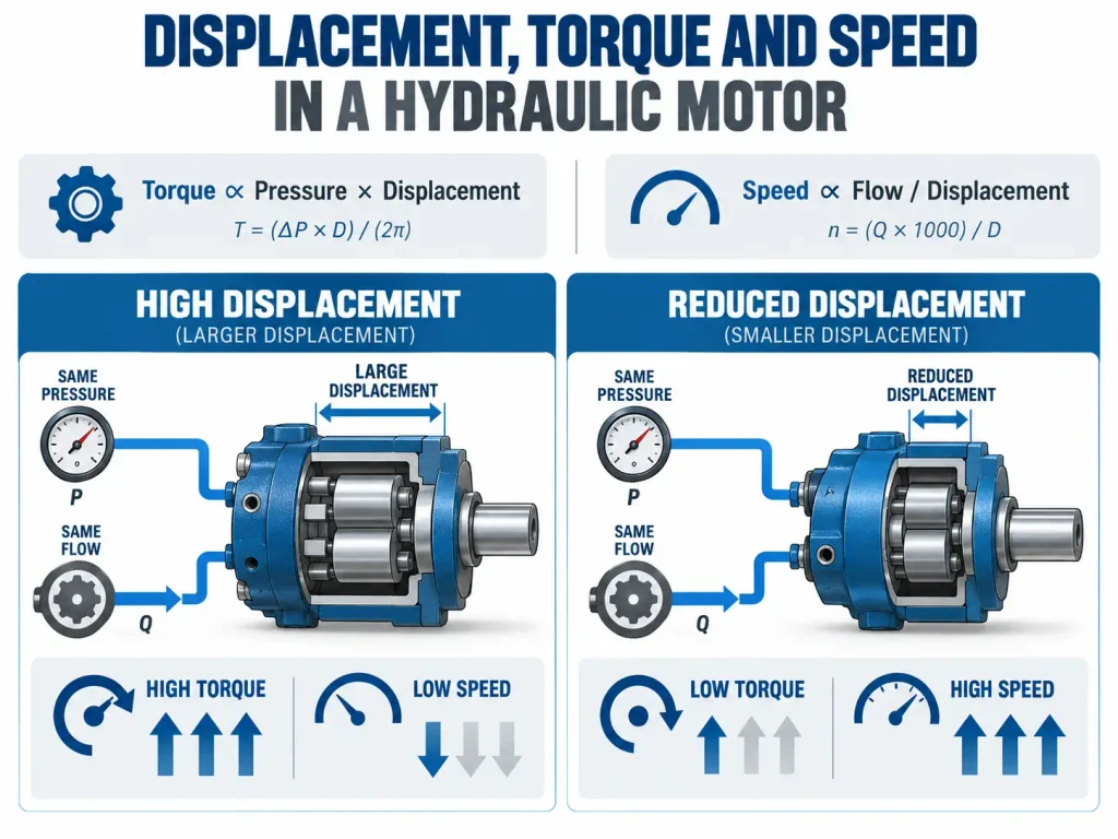
Displacement, the volume of oil required for one revolution of the output shaft, sets the relationship between torque and speed. For a given pressure differential, a larger displacement produces more torque and turns more slowly at the same flow, while a smaller displacement produces less torque and turns faster.
For a hydraulic motor the governing relationships are:
T = (Δp × Vg × ηm) / (2π)
n = (Q × ηv) / Vg
where the quantities and units are:
| Symbol | Quantity | SI unit | Common industrial unit |
| T | Output torque | N·m | N·m |
| Δp | Pressure differential across the motor | Pa | bar |
| Vg | Geometric displacement per revolution | m³/rev | cc/rev |
| Q | Inlet volumetric flow | m³/min | L/min |
| n | Output speed | rev/min | rev/min |
| ηm | Mechanical efficiency | dimensionless | dimensionless |
| ηv | Volumetric efficiency | dimensionless | dimensionless |
These relationships are written in coherent SI units, and values in bar, cc/rev or litres per minute must not be substituted into them directly. In industrial practice the same relationships are normally used in convenient forms:
T (N·m) ≈ (Δp (bar) × Vg (cc/rev) × ηm) / 62.83
n (rev/min) = (1000 × Q (L/min) × ηv) / Vg (cc/rev)
Effective Displacement and Piston Stroke
Piston stroke is determined mainly by the geometry of the eccentric mechanism or by the cam profile. Displacement per revolution then depends on the piston area, the working stroke, the number of working strokes per revolution and the number of chambers in service. All four have to be read together, which is why motors of similar physical size can have very different displacements. Suppliers of a piston motor range normally publish geometric displacement together with volumetric efficiency at defined pressure and speed, which is what makes a consistent comparison possible.
Two effects are often confused here. Displacement switching is a designed change in the volume taken in per revolution, brought about by the mechanism itself. Leakage is not a displacement change at all: it lowers volumetric efficiency, so the shaft turns more slowly than flow and displacement alone predict, and the shortfall grows with pressure, temperature and wear.
How Eccentricity and Hydraulic Switching Change Displacement
Not every radial piston motor offers a change in displacement, and the available mechanisms should not be described as if they were universal.
In eccentric or crankshaft designs, displacement can in principle be varied by changing the eccentricity of the journal, and a small number of designs use this approach. It requires a mechanism able to move the eccentric under load, which adds complexity.
In cam ring designs, a widely used method is internal hydraulic switching: the internal oil paths are reconfigured so that only part of the cam circumference is used as a working segment. Fewer working cam segments means less volume taken in per revolution, with no change to the external dimensions. Both methods reach the same result by different means, and neither can be assumed to be present.
Fixed, Dual and Variable Displacement Designs
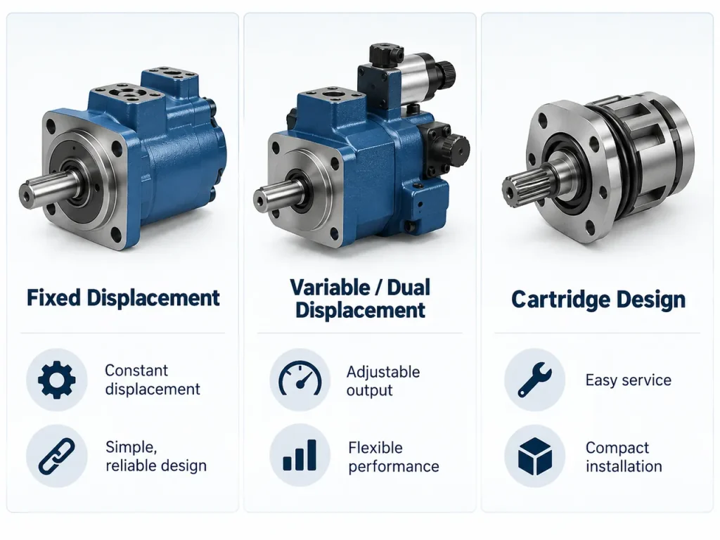
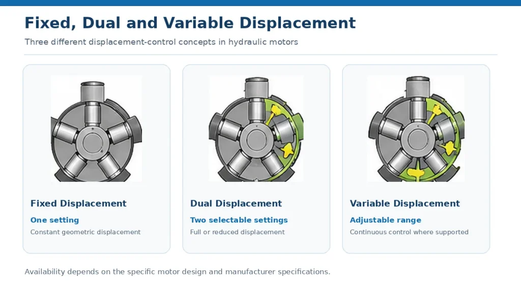
A fixed-displacement motor has one displacement, so speed follows flow and torque follows pressure differential in a single predictable relationship. A dual-displacement motor offers two settings, normally called full and reduced displacement. At full displacement the motor produces higher torque at a given pressure differential and its lowest speed for a given flow.
At reduced displacement, the motor runs faster at the same inlet flow while producing less torque at the same pressure differential. If the displacement is reduced by exactly 50%, the ideal speed doubles and the ideal torque halves, assuming unchanged flow, pressure differential and efficiency. Actual performance depends on the displacement ratio, operating conditions and manufacturer-rated speed limits, so published values for a specific series are more reliable than the idealised ratio.
A dual-displacement motor is not a continuously variable motor. It switches between two discrete displacements, whereas a variable-displacement motor can be adjusted through a range so that the torque and speed relationship is tuned continuously to the duty. Freewheeling is a third condition and should not be confused with reduced displacement: in a motor with freewheeling capability the pistons can be retracted so the contact elements lose contact with the cam surface, allowing the shaft to rotate without the motor being driven hydraulically. That is qualitatively different from full or reduced displacement operation, in which the pistons remain in contact and continue to transmit torque.
Advantages and Limitations of Radial Piston Motors
The performance value of the design lies in how much turning moment it produces from a compact unit, and how little rotational speed it needs to produce it.
The main advantages are:
- High torque density, so a comparatively small unit can produce a large turning moment.
- High starting torque from standstill, which lets a loaded machine begin moving without a clutch, gearbox or oversized motor.
- Tolerance of mechanical and hydraulic shock, suiting equipment that meets sudden loads and pressure peaks.
- Low internal leakage relative to several competing designs, which helps hold speed and load under pressure.
- Direct drive capability, removing the cost, losses and maintenance of a reduction gearbox.
- Long service life, provided the unit stays within its rated conditions and filtration, fluid temperature and maintenance are kept to specification.
The limitations matter equally:
- Mass and envelope, because the housing and bearings must carry substantial radial loads.
- Purchase cost, generally higher than for gear or vane motors of comparable speed and torque.
- A practical speed ceiling, above which other designs are more suitable.
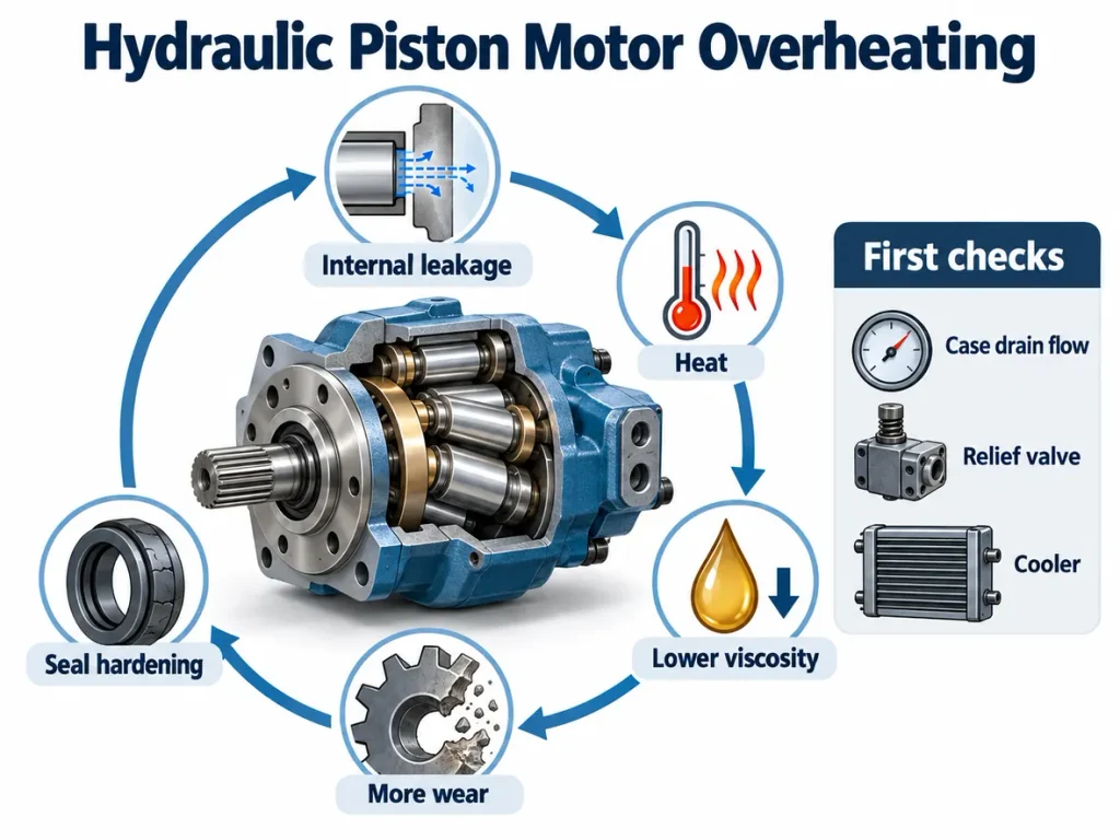
- Sensitivity to fluid cleanliness and case drain conditions, because internal clearances are small.
- A need for adequate cooling and attention to back pressure on the return line.
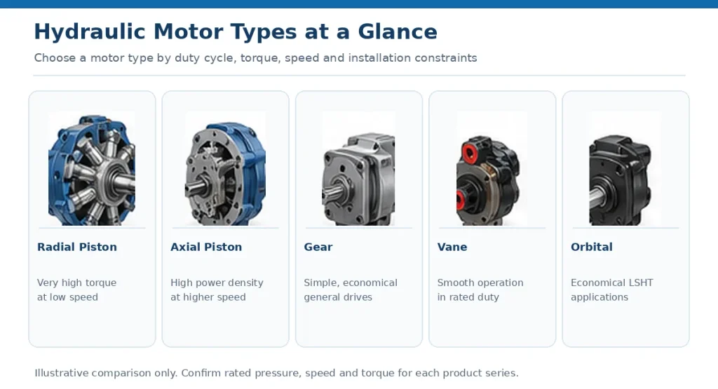
Choosing Between Radial Piston Motors and Other Motor Types
Choosing between motor types is a matter of matching the torque and speed requirement, the duty cycle and the installation constraints.
| Motor type | Selection focus | Typical pressure | Typical speed | Torque character |
| Radial piston | Low-speed, very high torque, heavy-load starting | High to very high | Low | Very high, available from standstill |
| Axial piston | Higher speed with high power density | High | High | High and smooth at speed |
| Gear | Simplicity and low cost | Low to medium | Medium | Moderate, less smooth |
| Vane | Smooth running in controlled conditions | Medium | Medium to high | Good, smoother than gear |
| Orbital (gerotor or geroler) | Economical low-speed, high-torque drive | Medium to high | Low to medium | High at low speed |
The pressure, efficiency and speed figures for each type are published for specific product series at defined test conditions and should not be read as the limits of an entire category. Series within one category differ substantially in rated pressure, allowable speed and internal leakage, so published data for the intended model is the only reliable basis for comparison.
A practical sequence is to establish the required continuous torque and speed range first, then check starting torque, then confirm the hydraulic supply on the machine, and finally weigh package size, mounting, braking and cost. Where the duty combines heavy loads, frequent starts under load and low rotational speeds, the radial piston motor is normally the first candidate; where higher speed and continuous rotation dominate, other designs offer a better balance.
Where Radial Piston Motors Are Used
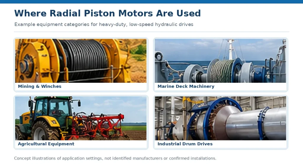
The applications share one characteristic: the machine has to move something heavy, slowly and reliably, often where a gearbox would be an unwanted complication.
Construction and Mining Equipment
Radial piston motors are used in selected construction and mining applications where high starting torque, low-speed control and resistance to changing loads are important. Typical examples include heavy-duty winches, direct-drive wheel systems, conveyor drives, drilling equipment and selected tunnel-boring machinery. Some specialised swing-drive systems also use radial piston technology, although many conventional excavator travel and swing drives use axial piston motors with planetary gearboxes. The appropriate design depends on the required torque, speed, shock loading and available installation space. Specifying suitable hydraulic parts for mining industry duty also means confirming that the motor is rated for the site’s shock, contamination and duty cycle, not only the nominal load.
Agriculture, Marine and Industrial Machinery
Agricultural and forestry machinery uses these motors where torque is needed at low speed in dusty or wet conditions. On vessels, deck machinery, anchor winches and towing equipment rely on the ability to control heavy loads at low speeds, and reliable load holding in these systems comes from appropriate braking or load-holding devices rather than from the motor alone. In industrial plant, plasticising screw drives, extrusion lines, hydraulic presses, rotary kilns and drum drives use the same principle, generally where a large turning moment is needed over a wide speed range.
Selection and Maintenance Essentials
Correct selection comes down to a small number of parameters, and correct maintenance comes down to protecting the internal clearances.
Establish the continuous and peak pressure, the required displacement, the working speed range, the starting torque under worst-case load, the mounting and braking arrangement, the permissible case drain and return-line back pressure, the required fluid cleanliness class, and the expected fluid and ambient temperatures. Performance figures are quoted at defined test conditions, and industry bodies such as the National Fluid Power Association publish guidance on how fluid power components are rated and compared, which helps in interpreting supplier data consistently.
Maintenance is largely a matter of protecting the running clearances and the oil film at the contact elements:
- Sample and analyse the fluid on a schedule for contamination and wear metals, and change the oil when the analysis indicates it is due.
- Replace filters at the specified intervals, and check that the filtration rating matches the cleanliness class the motor requires.
- Inspect seals, the case drain line and the drain pressure, since an obstructed drain raises internal pressure and shortens seal life.
- Monitor operating temperature and watch for changes in noise and vibration, which usually appear before a measurable loss of performance.
Where a machine requires a non-standard interface, mounting pattern or displacement, a custom hydraulic motor built to the application’s duty cycle is often more economical than adapting a catalogue unit with extra hardware.
FAQ
How Does Piston Arrangement Affect Torque Smoothness?
Torque smoothness depends on how many pistons produce torque at any instant and how evenly their contributions overlap. More pistons and a cam profile with more lobes may improve torque smoothness when combined with appropriate phasing and porting, but the pattern of piston positions matters more than the count alone, so a design with an even number of pistons and a suitable cam and porting arrangement can be smoother than one with fewer pistons arranged differently.
Can a Radial Piston Motor Be Operated as a Pump?
Some radial piston motors are rated for pump operation and can be driven in that mode within their published limits, but this is not a general property of the category. Confirmation is needed for the rated pump-mode conditions, the porting and timing arrangement, internal lubrication at the intended speed and direction, case drain provisions, and the mounting and shaft loading.
What Limits the Maximum Speed of a Radial Piston Motor?
The main limits are the reciprocating speed of the pistons and contact elements, the ability of the inlet passages to fill each chamber without cavitation, and the heat generated as speed and pressure rise together. Because a large displacement comes from substantial piston areas and long strokes, both the inertia and the volume to be filled per revolution are high, which places the practical speed ceiling lower than for axial piston or vane designs. Above it, filling losses and wear at the contact elements rise sharply, which is why these motors are normally specified for low-speed duty.