Hydraulic systems power some of the heaviest and most precise machines in industry, from excavators and mining drills to injection molding presses and offshore winches. In each of them, one component decides how much force the machine can generate: the pump. Gear and vane designs handle light and medium duty work well, but once system pressure climbs past roughly 250 bar and efficiency stops being optional, engineers turn to the hydraulic piston pump. Yet its internal mechanics remain a black box for many buyers, which makes it hard to judge whether a given unit will suit an application.
A hydraulic piston pump is a positive displacement pump that uses pistons reciprocating inside cylinder bores to draw hydraulic fluid in on one stroke and force it out under pressure on the next. Rotating motion from a drive shaft is converted into reciprocating piston motion by a swash plate, a bent axis, or an eccentric cam ring, while a valve plate or distributor routes fluid in and out in sync with each stroke. Because fluid is physically displaced from a sealed chamber rather than carried between gear teeth or sliding vanes, piston pumps deliver the highest volumetric efficiency, the highest continuous pressure ratings, and the finest flow control of any common hydraulic pump design.
This guide covers the working principle, the two main families of piston pumps, the parts inside them, and the rules that decide whether one belongs in your system.
What Is a Hydraulic Piston Pump?
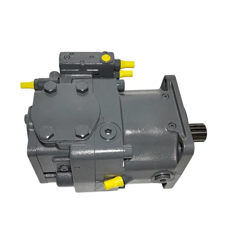
A hydraulic piston pump is a volumetric pump in which pistons reciprocate inside precisely machined bores, alternately enlarging and shrinking a sealed chamber to move fluid. It sits within the wider family of Types of Hydraulic Pumps alongside gear and vane pumps, but separates itself through pressure capability, efficiency, and controllability rather than a different energy conversion concept.
All hydraulic pumps convert mechanical energy into hydraulic energy stored in fluid as pressure and flow, but piston pumps sit at the top of that hierarchy. Their sealing surfaces are flat metal interfaces measured in microns, keeping internal leakage low even at high pressure. The trade-off is higher cost and strict filtration requirements.
The Positive Displacement Principle
A positive displacement pump traps a fixed volume of fluid and expels it regardless of downstream pressure. Two consequences follow:
- Output flow depends on pump geometry and drive speed, not system pressure.
- If the outlet is blocked while the pump turns, pressure rises until something yields, which is why these circuits need a relief valve.
Piston Pump vs Gear and Vane Pump
| Criterion | Gear Pump | Vane Pump | Piston Pump |
| Continuous pressure | 100 to 250 bar | 100 to 210 bar | 250 to 450 bar |
| Volumetric efficiency | 80 to 90 percent | 85 to 92 percent | 93 to 98 percent |
| Displacement control | Fixed only | Fixed or variable | Stepless variable |
| Contamination tolerance | High | Moderate | Low |
| Relative cost | Lowest | Moderate | Highest |
How Does a Hydraulic Piston Pump Work?
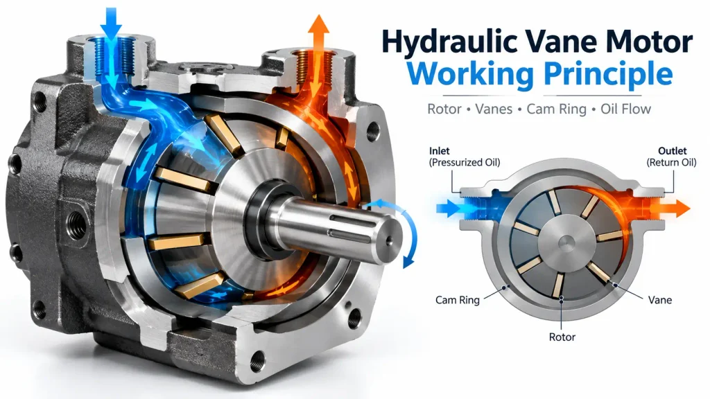
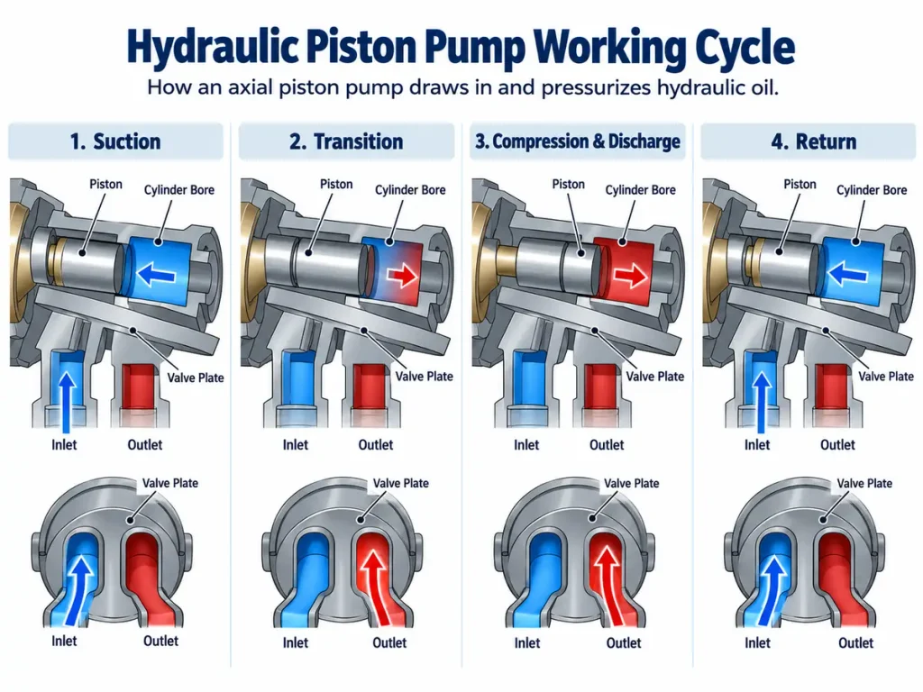
It works by repeatedly changing the volume of a sealed chamber. As a piston retracts, the chamber expands and creates a partial vacuum that pulls fluid in through the suction port. As the piston is pushed back, the chamber contracts, pressure rises, and trapped fluid is forced out through the discharge port. A rotating valve plate opens the suction and discharge passages at the right moment in each revolution, so the cycle repeats continuously.
The Suction and Discharge Cycle
The cycle of a single piston unfolds in four stages:
- Suction stroke. The piston retracts, volume increases, internal pressure drops below tank pressure, and fluid is drawn in through the suction window. The inlet must be unrestricted.
- Transition to discharge. The piston reaches bottom dead centre and the valve plate seals the chamber from the inlet.
- Compression and discharge. Rotation drives the piston back in, volume shrinks, pressure exceeds system pressure, and fluid leaves through the discharge window.
- Transition to suction. At top dead centre the cycle restarts, with window timing preventing backflow.
How Displacement Is Controlled
Displacement is the volume moved per revolution, and controlling it is what makes piston pumps valuable.
- Fixed displacement. Stroke never changes, so flow depends only on drive speed. Excess flow is dumped across a relief valve and becomes heat.
- Variable displacement. Stroke is set by the swash plate angle or cam ring offset. A steeper angle means more flow, and at zero angle the pump delivers nothing while still rotating.
Flow control is therefore independent of engine speed, which is what precision work requires.
What Are the Different Types of Hydraulic Piston Pumps?
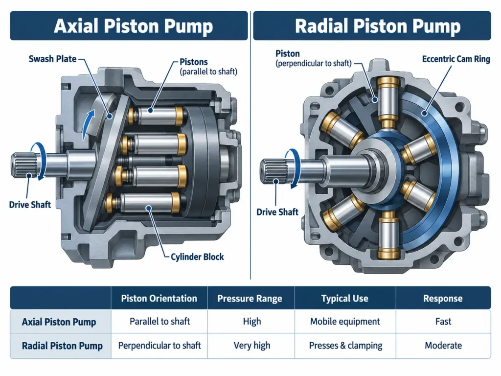
Piston pumps fall into two families defined by piston direction relative to the drive shaft. Axial piston pumps arrange pistons parallel to the shaft inside a rotating cylinder block, splitting further into swash plate and bent-axis designs. Radial piston pumps arrange pistons perpendicular to the shaft, like spokes of a wheel, and are chosen when pressure requirements exceed what axial designs handle. Both can be built with fixed or variable displacement.
Axial Piston Pumps
Seven to nine pistons sit in bores arranged in a circle around the shaft, all parallel to it. As the cylinder block rotates, the piston ends ride against an angled surface that forces each piston in and out once per revolution.
- Swash plate design. A flat angled disc sets the stroke. Pistons push against it through slipper pads, and a return plate pulls them back during suction. The angle can be adjusted hydraulically, making this the most common variable arrangement in mobile machinery.
- Bent axis design. The cylinder block sits at an angle to the shaft and is driven through a universal joint, with stroke set by the bend angle. These tolerate higher speeds and pressure for a given size, with a less compact envelope.
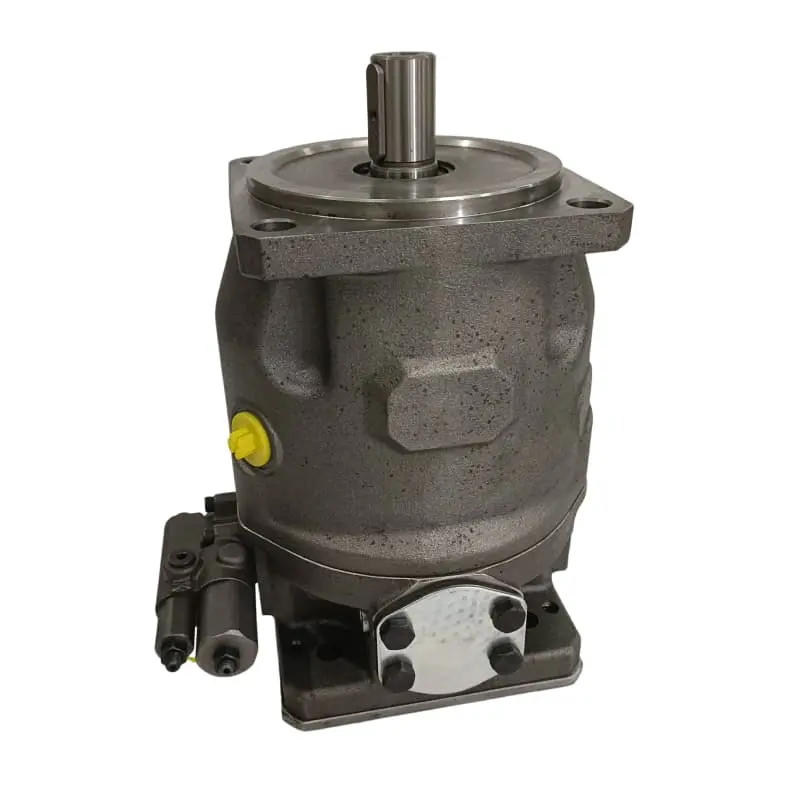
Axial pumps offer high power density and fast response, which is why they dominate construction and industrial automation. They also demand very clean fluid, because the sliding interfaces are unforgiving of abrasives. Units for these duties are commonly sourced from a Piston Pump Manufacturer experienced in high-pressure mobile applications.
Radial Piston Pumps
Pistons sit in bores radiating outward from the shaft, their outer ends riding against an eccentric ring or cam profile. As the block rotates, eccentricity pushes each piston inward and lets it travel outward again.
- Very high pressure capability, commonly 400 to 700 bar, because load paths are short.
- Strong contamination tolerance, since the piston-to-cam contact is well supported.
- Lower maximum shaft speeds, because pistons see high centrifugal loading.
- Larger size and cost, plus complex collector plumbing.
Radial pumps suit hydraulic presses and high-pressure clamping, where pressure matters more than compactness.
Axial vs Radial Comparison
| Parameter | Axial | Radial |
| Piston orientation | Parallel to shaft | Perpendicular to shaft |
| Pressure range | 200 to 450 bar | 400 to 700 bar |
| Maximum speed | High | Moderate to low |
| Variable control | Stepless, fast response | Slower to adjust |
| Typical duty | Mobile equipment | Presses, high-pressure clamping |
Below roughly 400 bar with a machine that has to move, an axial design is the better economic choice. Above 500 bar, a radial design earns its cost.
What Are the Main Components of a Hydraulic Piston Pump?
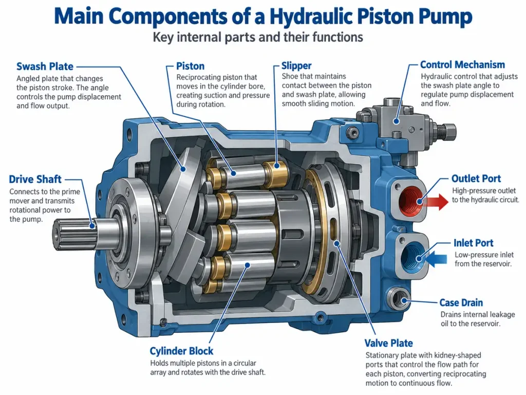
The main components are the cylinder block, pistons and slipper assemblies, the drive shaft, the swash plate or cam ring, the valve plate or distributor, and the displacement control mechanism. The cylinder block houses the pistons, the shaft supplies rotation, the angled surface converts rotation into stroke, and the valve plate governs when each chamber connects to suction or discharge. The control mechanism adjusts stroke length to set flow.
The housing and its fittings belong to broader Hydraulic Pumps Manufacturer product families, but the internal logic is consistent across designs.
Cylinder Block, Pistons, and Slippers
The cylinder block is a hardened rotating body with honed bores whose accuracy relative to the pistons determines internal leakage and volumetric efficiency. Pistons are lapped to match their bores as a matched pair, so both should be replaced together.
Slipper assemblies provide a hydrostatic bearing surface fed by a thin film of pressurised oil, and mount the return mechanism that pulls pistons back during suction. Slipper wear produces bronze particles in the case drain filter long before the pump fails outright, making that filter a valuable diagnostic point.
Drive Shaft, Swash Plate, and Cam Ring
The shaft transmits torque and is supported by heavy-duty bearings that absorb the axial reaction loads piston pumping generates. The swash plate, or the eccentric cam ring in radial pumps, converts rotary motion into reciprocating motion. In variable units it is mounted on trunnion bearings so a control piston can change its angle. Wear or sticking here causes sluggish flow response rather than total pressure loss.
Valve Plate and Control Mechanism
The valve plate is a stationary plate containing two kidney-shaped openings connected to the suction and discharge lines. As each bore sweeps past them, its connection switches automatically, giving valve timing with no moving valves.
The control mechanism sets displacement. It may be a pressure compensator, a load-sensing control that matches flow to actuator demand, a torque-limiting control that caps the product of pressure and flow, or a manual or electro-proportional control.
Most piston pumps also carry a case drain. A small amount of oil intentionally leaks past the pistons to lubricate them and must leave the housing freely. If the drain line is blocked, case pressure rises and pushes oil past the shaft seal.
The Seven Principles of Hydraulics Behind a Piston Pump
The seven principles describe how force, pressure, flow, and resistance interact in a closed system: pressure is transmitted undiminished through a confined fluid, pressure is created by resistance to flow rather than by the pump, flow rate determines actuator speed, force equals pressure multiplied by area, hydraulic fluid is treated as incompressible, fluid follows the path of least resistance, and energy removed as pressure drop reappears as heat. A piston pump is the most efficient device available for applying the first, third, and fourth of these to real machinery.
- Pascal’s law. Pressure in a confined fluid is transmitted equally in every direction, so one small pump can actuate several cylinders.
- Resistance creates pressure. The pump generates only flow, so against an open centre circuit it develops almost no pressure.
- Flow determines speed. Actuator velocity is proportional to flow, not pressure, which is why variable displacement changes speed without touching the throttle.
- Force equals pressure times area. Modest pressure on a large piston area generates enormous force, the basis of all hydraulic lifting.
- Fluid is effectively incompressible. This enables stiff response and allows micron-tolerance sealing. Fluid power references such as the Hydraulic machinery overview treat this as foundational.
- Flow takes the path of least resistance. Internal leakage through worn clearances reduces usable output, which is why worn pumps deliver less flow as oil warms up.
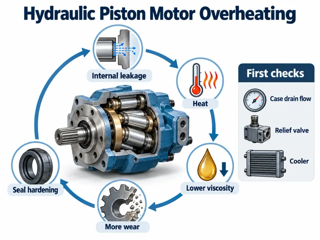
- Pressure drop becomes heat. Relief dumping, undersized lines, and excessive leakage all raise oil temperature.
Advantages and Limitations of Hydraulic Piston Pumps
Piston pumps offer the highest efficiency of any common pump type, continuous pressure ratings reaching 450 bar and beyond, stepless variable displacement for precise flow and speed control, and low noise with minimal pulsation. Their main limitations are high purchase cost, strict fluid cleanliness requirements, and expensive repair when precision internal components wear.
| Advantages | Limitations |
| Highest pressure capability of the three main designs | Highest initial cost |
| Volumetric efficiency of 93 to 98 percent | Requires fine filtration to a defined cleanliness class |
| Stepless variable displacement with fast response | Less contamination-tolerant than gear or vane pumps |
| Low pulsation and quiet operation | Matched piston and bore pairs must be replaced together |
| Long life under clean, correct operating conditions | Sensitive to inlet restriction and aeration |
Applications and How to Select a Piston Pump
Piston pumps are selected by matching five parameters to the application: working and peak pressure, required flow and displacement, available drive speed, fluid properties, and the operating environment including contamination risk and duty cycle. These matter more than any single datasheet specification, because a pump correct on pressure but wrong on speed or cleanliness will fail ahead of schedule.
Typical Applications by Industry
- Construction. Excavators, loaders, and concrete pumps use variable axial pumps for boom, bucket, and travel circuits, a segment served by dedicated Hydraulic Parts for Construction Industry system packages.
- Mining and metallurgy. Drilling rigs, crushers, and presses demand continuous high pressure in dusty conditions.
- Agriculture. Hitch and implement circuits use piston and vane pumps split by pressure demand.
- Marine and offshore. Deck winches and steering gear need dependable high-pressure performance.
- Industrial automation and aerospace. Injection molding machines use variable pumps to cut energy use during holding phases, while aircraft systems rely on axial pumps.

Piston Pump Selection Checklist
- Working and peak pressure. Distinguish continuous, intermittent, and peak ratings, and never select on peak rating alone.
- Required flow. Calculate flow at maximum actuator speed and divide by drive speed to obtain displacement.
- Drive speed range. Running below minimum speed causes poor lubrication.
- Fluid type and viscosity. Mineral oil, water-glycol, and synthetics impose different clearances, and viscosity governs chamber filling.
- Cleanliness and filtration. This single decision influences service life more than any other.
- Mounting, ports, and control type. Confirm flange standard, shaft type, rotation direction, and control mode.
- Duty cycle and environment. Continuous duty in hot or dusty conditions shortens service intervals.
Common Faults and Maintenance
Most piston pump failures trace to three root causes: fluid contamination, inadequate suction leading to cavitation, and internal leakage through worn piston, slipper, or valve plate surfaces. Because these causes produce predictable symptoms, a symptom-to-cause approach resolves most field problems before the pump is dismantled. Cleanliness benchmarks such as the ISO 4406 classification provide a practical filtration target, and the standard is published by the International Organization for Standardization.
| Symptom | Likely Cause | Diagnostic Action |
| Loud whining or screaming | Cavitation from restricted inlet or cold oil | Check suction strainer, line size, and viscosity |
| Low pressure when oil is hot | Internal leakage through worn clearances | Measure case drain flow against specification |
| No flow at normal speed | Broken return plate or seized pistons | Inspect return mechanism and piston freedom |
| Sluggish control response | Sticking control piston or contaminated spool | Check control oil cleanliness and inspect spool |
| Oil weeping from shaft seal | Excessive case pressure from restricted drain | Verify drain line size and tank termination |
Three habits protect a pump better than any repair. Sample and analyse fluid on a fixed interval, tracking particle counts and wear metals. Change filtration elements before they go into bypass. Keep the suction side clean, because most catastrophic failures begin with a clogged inlet strainer nobody notices in time.
Repair is a specialist activity, since internal components are matched pairs with micron-level clearances. When a pump fails and the application needs a displacement, mounting interface, or control characteristic a catalogue unit does not provide, specifying a Custom Hydraulic Pump built to the original interface is often more practical than adapting a standard model.
FAQ
How does a fixed displacement piston pump differ from a variable displacement one?
A fixed displacement pump moves the same volume every revolution, so flow changes only with drive speed. A variable displacement pump alters stroke length by adjusting swash plate angle or cam eccentricity, which eliminates the energy waste of dumping excess flow across a relief valve.
Can a hydraulic piston pump be used as a hydraulic motor?
Frequently yes, particularly axial units with a valve plate rather than check valves, since pump and motor share the same geometry. Valve plate timing must suit bidirectional operation, the case drain must work in both directions, and lubrication at low speed must be adequate, because a motor may spend long periods stalled under load.
How can you extend the service life of a hydraulic piston pump?
Three factors dominate. Control fluid cleanliness, keeping particle counts within the specified class. Protect the suction side by sizing inlet lines generously and keeping strainers clean. Manage heat, since high oil temperature thins the fluid and reduces the hydrostatic film in the slipper bearings.