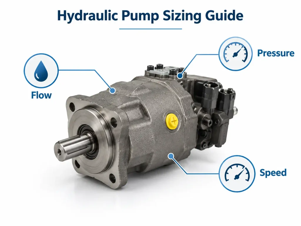
Hydraulic motors do unglamorous work on construction sites and farms: slewing an excavator, turning a conveyor, hauling a winch line. They all do the same basic job. What separates them is how each handles torque, speed, pressure, efficiency and service life, and a motor that runs happily in one machine can wear out early in another.
A hydraulic motor is a positive-displacement actuator that converts hydraulic pressure and flow into continuous rotary mechanical power. Choosing the right one depends mainly on the required torque, speed, operating pressure, duty cycle, and installation conditions.
The rest of this article covers how a hydraulic motor works, the design families you will meet in a catalogue, how to size one from torque and flow, and which type is genuinely most efficient for a given machine.
What Is a Hydraulic Motor and How Does It Work?
A hydraulic motor converts hydraulic energy into rotary motion: flow primarily determines speed, while pressure acting on motor displacement produces torque.
That second half is where confusion starts. The same pressure acting on a small displacement gives a modest turning force, and on a large one a heavy one. Displacement sits between them, and rotary actuators are rated on all three together.
Inside the housing, pressurised oil acts on a rotating group, and the pressure difference creates a turning force the shaft hands to the load. Open the flow and the shaft spins faster; raise the pressure or fit a larger displacement and more torque appears.
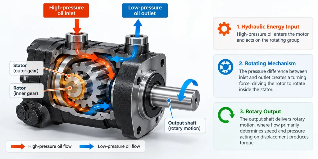
The Core Components of a Hydraulic Motor
The internals differ between designs, but most motors share the same set:
- A housing, containing the rotating group and carrying the ports
- A rotor, cylinder block, gear set or vane assembly, depending on design
- A valve plate or distribution mechanism for the displacement chambers
- An output shaft
- Bearings sized for the radial and axial loads
- Inlet and outlet ports
- A case drain port, on many designs though not all
The case drain carries internal leakage back to tank and keeps housing pressure inside the manufacturer’s limit. Leaving it uncoupled or blocked downstream lets that pressure climb, and the seal takes the strain.
From Fluid Pressure to Rotary Torque
Whatever the moving parts, the principle holds: high-pressure oil pushes on gears, vanes, pistons or an orbital element, and that force turns the shaft.
Three torque figures matter during selection:
- Starting torque, which gets the load moving from rest
- Running torque, which keeps it moving under load
- Stall or breakaway torque, needed to restart or hold a stalled load
None reach the shaft at full strength, because friction and internal leakage take a share, so theoretical and actual torque never match.
Hydraulic Motor vs Hydraulic Pump vs Electric Motor
Each moves energy differently:
- An electric motor turns electrical energy into mechanical energy
- A hydraulic pump turns mechanical energy into hydraulic energy
- A hydraulic motor turns hydraulic energy back into rotary mechanical energy
Follow the chain through a machine: engine or electric motor, hydraulic pump, control valve, hydraulic motor, mechanical load. Some positive-displacement designs run either way in principle, but not every pump is a spare motor, because porting, bearings, lubrication, seals and case pressure limits are often set for one direction of energy flow.
What Are the Different Types of Hydraulic Motors?
Hydraulic motors are commonly grouped into gear, vane, piston and orbital designs, with further distinctions such as fixed versus variable displacement and axial versus radial piston arrangements.
Each design trades cost, pressure, speed range and efficiency differently, so pick the compromise first.
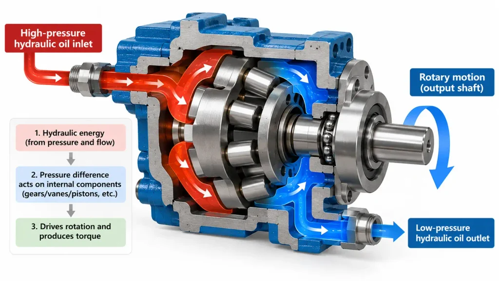
Gear Motors
A gear motor is one of the simplest hydraulic motor designs: two meshing gears in a housing, driven by oil pressure on the gear faces. Its straightforward construction makes it economical and more tolerant of contamination than precision hydraulic motor designs. They suit moderate pressure and higher speeds, and appear in fan drives, conveyors and auxiliary circuits, where a hydraulic gear motor balances price, speed and toughness. Leakage is the trade-off: efficiency sits below a piston motor’s and declines as the gears wear.
Vane Motors
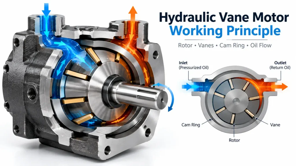
Vane motors slide their vanes inside a rotor, against an eccentric or shaped cam ring, and the chambers between them fill and empty as it turns. Rotation is smooth and quiet, which suits medium-speed industrial drives. Balanced designs relieve much of the radial load on the shaft. The main limitation is fluid cleanliness: a vane motor tolerates contamination less well than a gear motor.
Piston Motors: Axial and Radial
Two arrangements sit under this heading. In an axial piston motor the pistons run parallel to the shaft, and a swash plate or bent-axis mechanism converts their stroke into rotation. These sit at the high-pressure, high-efficiency end of the range, and many offer variable displacement.
Radial piston motors stand the pistons up around the shaft instead. The long stroke produces very smooth torque at low speed, and some designs hold that smoothness down to extremely low rotational speeds. Piston motors are the usual answer for high-pressure duty, though not automatically right for every machine.
Orbital Motors: Gerotor and Geroller
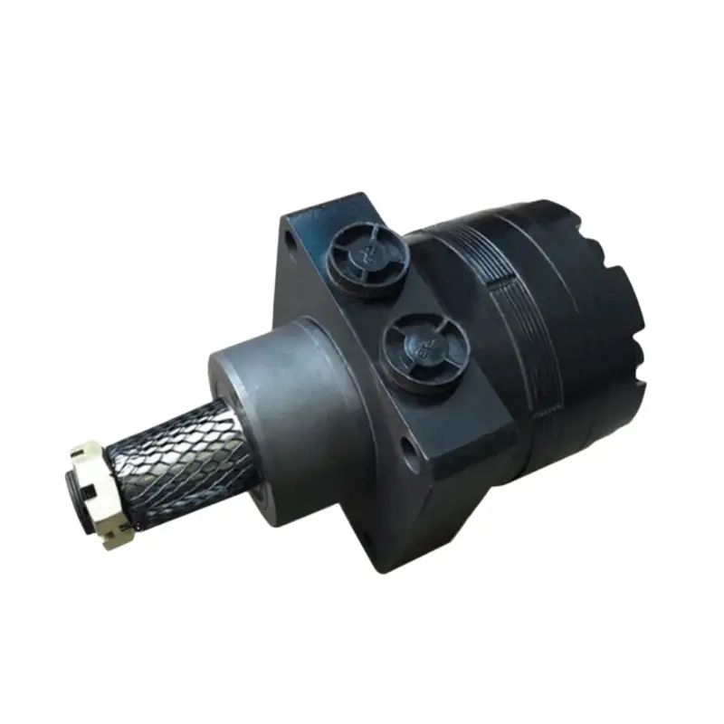
An orbital motor pairs an inner rotor with an outer stator carrying one more tooth, and the chambers between them expand and contract as the rotor orbits. This is the classic low-speed, high-torque layout: strong starting torque in a compact body that can drive a load directly, taking a gearbox and its losses out of the drivetrain. Geroller versions add rollers between rotor and stator, cutting sliding friction and improving starting performance over a basic gerotor.

Type Comparison at a Glance
| Motor Type | Pressure Capability | Speed Characteristic | Torque Characteristic | General Efficiency Trend | Cost | Contamination Sensitivity | Typical Applications |
| Gear | Moderate | Higher speeds | Moderate, with ripple | Low | Low | Tolerant | Fan drives, conveyors, auxiliaries |
| Vane | Moderate to high | Medium, smooth | Moderate, smooth | Moderate | Moderate | Sensitive | Medium-speed drives |
| Axial piston | High | Medium to high, controllable | High, variable options | High | Higher | Sensitive | Mobile drives, hydrostatic transmissions |
| Radial piston | High | Low to medium | Very high at low speed, smooth | High | Higher | Sensitive | Winches, hoists, heavy rotary drives |
| Orbital (gerotor, geroller) | Moderate | Low, stable | High starting torque | Moderate | Low to moderate | Fairly tolerant | Conveyors, implements, wheel drives |
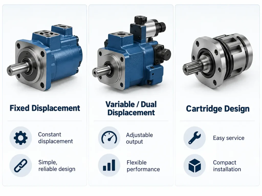
Fixed or variable is a separate decision: a fixed-displacement motor changes speed with flow alone, a variable unit trades speed against torque internally.
Once the motor family is narrowed down, the next step is to size it against the actual load, speed and duty cycle.
How to Choose the Right Hydraulic Motor?
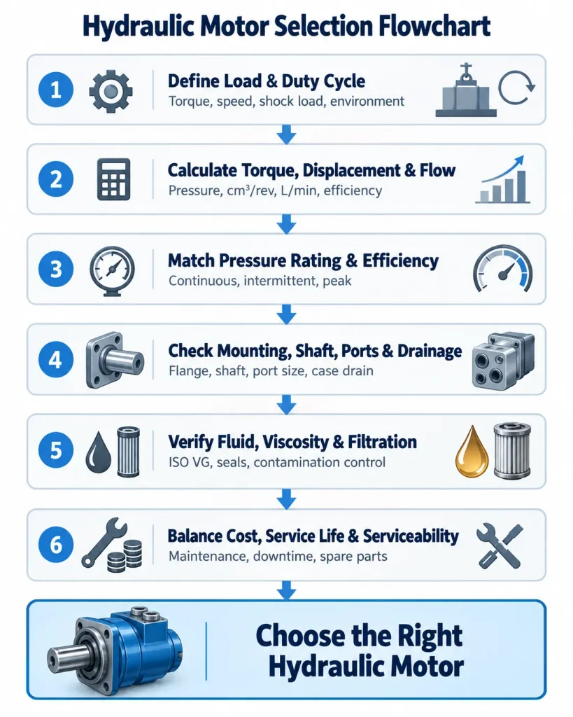
Choosing a hydraulic motor comes down to four questions: how much torque is required, how fast the load must rotate, what pressure is available, and what duty cycle and operating environment the motor must survive.
Work from the duty cycle, not the worst case you can imagine. A motor sized for a peak reached twice a week runs inefficiently the rest of its life.
Step 1: Define the Load, Speed and Duty Cycle
Start with the load. A continuous load is steady and easy to predict; an intermittent one arrives in defined phases; a shock load can briefly multiply the torque the motor must absorb. Inertia during acceleration adds to the demand, and starting torque often sits well above running torque. Then settle the rating the duty deserves: continuous, intermittent, or a mix. Temperature, vibration, corrosive exposure and noise limits belong here too, since they can rule out a design as fast as the load does.
Step 2: Calculate Displacement, Torque and Flow
Sizing starts with one relationship:
T theoretical (Nm) = pressure differential (bar) x displacement (cm³/rev) / 62.8
The shaft receives less, because friction takes a share:
T actual = T theoretical x mechanical efficiency (ηm)
Speed follows from flow and displacement:
n theoretical (rpm) = flow (L/min) x 1000 / displacement (cm³/rev)
and the measured figure lands lower, because some oil slips past instead of driving the rotating group:
n actual ≈ flow (L/min) x 1000 x volumetric efficiency (ηv) / displacement (cm³/rev)
Read the two together and a common mistake appears. A larger displacement raises the torque available from a given pressure, but it also needs more flow to reach the same speed, so displacement and speed are not locked in an inverse relationship. Check the result against the manufacturer’s curves at the point you expect, not a nominal rating. Early sizing sometimes carries a margin of roughly 10 to 20 percent, but the final figure should come from the manufacturer’s continuous, intermittent and peak ratings.
Step 3: Match the Pressure Rating and Efficiency Target
Pressure ratings come in three forms and are not interchangeable. Continuous pressure can be held indefinitely, intermittent pressure applies for limited periods, and peak pressure is a brief, occasional limit. Size on peak pressure and the motor will not last long.
Efficiency splits three ways as well. Volumetric efficiency accounts for flow lost to leakage, mechanical efficiency measures how much generated torque reaches the shaft, and overall efficiency combines the two. A more efficient motor sheds less heat and asks less of the cooling system.
Step 4: Verify Mounting, Shaft, Port and Drainage
Many sound selections come undone where the motor has to meet the machine. Check the mounting flange and pilot dimensions, the shaft type and its load limits, and the coupling alignment. Misalignment rarely shows on the drawing, only in a failed bearing months later.
Ports have to match the circuit, and lines should be sized so oil velocity and pressure drop stay reasonable without throttling the motor ports. Drainage gets overlooked more than anything else: many motors need an external case drain once housing pressure can exceed the manufacturer’s limit, which is common in series circuits. Where a standard unit will not fit, a custom hydraulic motor can be specified with a different flange, shaft, port orientation, seal material, or relief and crossover valve arrangement.
Step 5: Select Fluid, Viscosity and Filtration
The fluid has to suit the circuit and the motor at once. Keep viscosity inside the manufacturer’s ISO VG range: too thin and internal leakage rises, too thick and flow resistance climbs while efficiency falls. Seal material matters just as much with fire-resistant or environmentally friendly fluids.
Contamination is one of the leading reasons hydraulic motors wear out early, so filter rating, oil temperature control and oil monitoring belong in the selection rather than a maintenance note. Guidance on viscosity selection is published by bodies such as the National Fluid Power Association.
Step 6: Balance Cost, Service Life and Serviceability
Purchase price is one line in the total. Energy consumption, maintenance, downtime, repairability and spare parts availability all add to it, and size and weight decide what fits. The cheapest motor on the quotation is rarely the cheapest to own.
Which Type of Hydraulic Motor Is the Most Efficient?
Piston motors, especially well-designed axial piston motors, generally achieve the highest overall efficiency in high-pressure hydraulic systems, while gear motors usually prioritise simplicity, durability and cost over peak efficiency.
Why piston motors lead comes down to fit and balance: pistons and bores are matched closely and hydrostatically balanced, so leakage and friction stay low as pressure climbs. Vane motors give smooth, moderate-efficiency operation at medium pressure. Orbital motors are strongest at low speed, where high starting torque lets them drive the load directly.
| Motor Type | Volumetric Efficiency | Mechanical Efficiency | Overall Efficiency Trend | Best-Fit Duty |
| Gear | Lower, and worsens with wear | Moderate | Lowest of the common types | Simple, higher-speed duty |
| Vane | Moderate to good | Moderate to good | Moderate | Smooth medium-speed duty |
| Axial piston | Generally the highest | Generally the highest | Highest at high pressure | High-pressure, variable duty |
| Radial piston | High | High, smooth at low speed | High | Very low-speed, high-torque duty |
| Orbital (gerotor and geroller) | Good at low speed | Strong starting torque | Competitive at low speed | Direct-drive low-speed duty |
None of those figures are universal. Efficiency moves with design, size, pressure and speed, so a datasheet comparison only means something at a matched operating point. Standards such as ISO 8426 define how displacement is determined under steady conditions.
The point that gets missed is this. The most efficient motor on a datasheet is not always the most efficient choice for the machine. A winch working at low speed and high torque may do better with an orbital or radial piston motor, because direct drive removes a gearbox and its losses from the drivetrain. The system can come out ahead even when the motor is not the highest-efficiency type. Asking a piston motor manufacturer for data at the real operating point settles the question faster than any table.
Installation, Startup and Maintenance Essentials
Many early hydraulic motor failures are linked to installation, contamination, lubrication, drainage, or operating conditions rather than the basic motor design itself.
Installation is mostly about checking the basics before the machine is pressurised: rotation direction, shaft alignment, hydraulic lines supported so their weight does not hang on the motor ports, and a case drain arrangement that suits motor and circuit. Inspect the fittings too.
At startup, pre-fill the motor where the manufacturer calls for it, vent trapped air, and begin at low pressure and low speed. Bring the load up gradually while watching leakage, noise, pressure and temperature. Applying full load immediately during initial startup can increase the risk of inadequate lubrication, trapped air and premature wear.
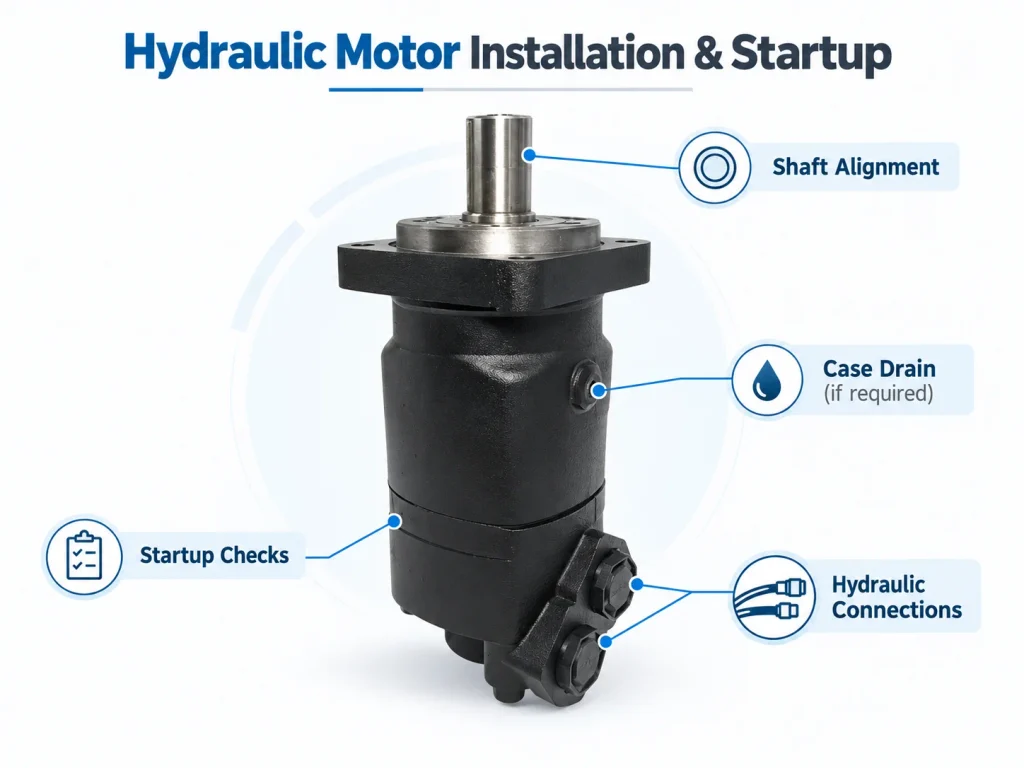
With the machine running, the job is keeping fluid and conditions inside specification: fluid cleanliness, filters on schedule, oil temperature, case drain flow, and any change in the sound of the drive.
| Symptom | Likely Cause | Recommended Check |
| Shaft seal leakage | High case pressure, blocked drain, worn seal | Drain routing, back pressure, seal condition |
| Overheating | Internal leakage, low fluid level, cooling | Oil temperature, cooler, viscosity |
| Low output torque | Internal wear, low supply pressure, setting | System pressure, differential, leakage |
| Abnormal noise or vibration | Air entrainment, cavitation, misalignment | Inlet condition, alignment, shaft loading |
| Excessive case drain flow | Worn rotating group | Leakage rate, service hours, condition |
If a motor needs rebuilding rather than replacing, the decision rests on the condition of the rotating group and housing, the cause of failure, and the cost of repair plus downtime. A hydraulic motor manufacturer normally supplies the service limits that make the call objective.
FAQ
Can a hydraulic motor be used as a hydraulic pump?
Some positive-displacement designs are reversible in principle, but a motor should only serve as a pump where the manufacturer approves it, because direction, lubrication, porting and pressure conditions can all differ.
What is the difference between a hydraulic motor and a hydraulic pump?
A pump takes mechanical energy from a prime mover and converts it into hydraulic energy. A motor runs the conversion the other way, turning hydraulic energy back into rotary mechanical output. They are complementary parts of one circuit.
What happens if the case drain line is blocked or not connected?
Housing pressure can rise until it exceeds what the seal can hold, increasing seal stress and leakage risk and, in severe cases, damaging the seal. Requirements vary by design, so confirm the arrangement rather than assuming.
How do you size a hydraulic motor for torque and speed?
Torque sets the combination of displacement and pressure required, while speed sets the flow needed for that displacement. Final selection also has to account for efficiency, duty cycle and the manufacturer’s ratings.
How do you know when a hydraulic motor should be replaced instead of repaired?
Replacement usually makes sense once internal leakage becomes excessive, overheating keeps returning, the rotating group or housing is damaged, or repair cost approaches the price of a new unit.