When a hydraulic machine loses speed, holds pressure badly or makes new noises, the fault is rarely in the cylinder or the pump. It usually sits in the control layer between them, the component that decides where the oil goes, at what pressure and how fast. A hydraulic control valve holds micrometre clearances at high pressure, so it degrades gradually, and the pressure, flow and cleanliness ratings published by any Hydraulic Valve Manufacturer are the baseline to compare against.
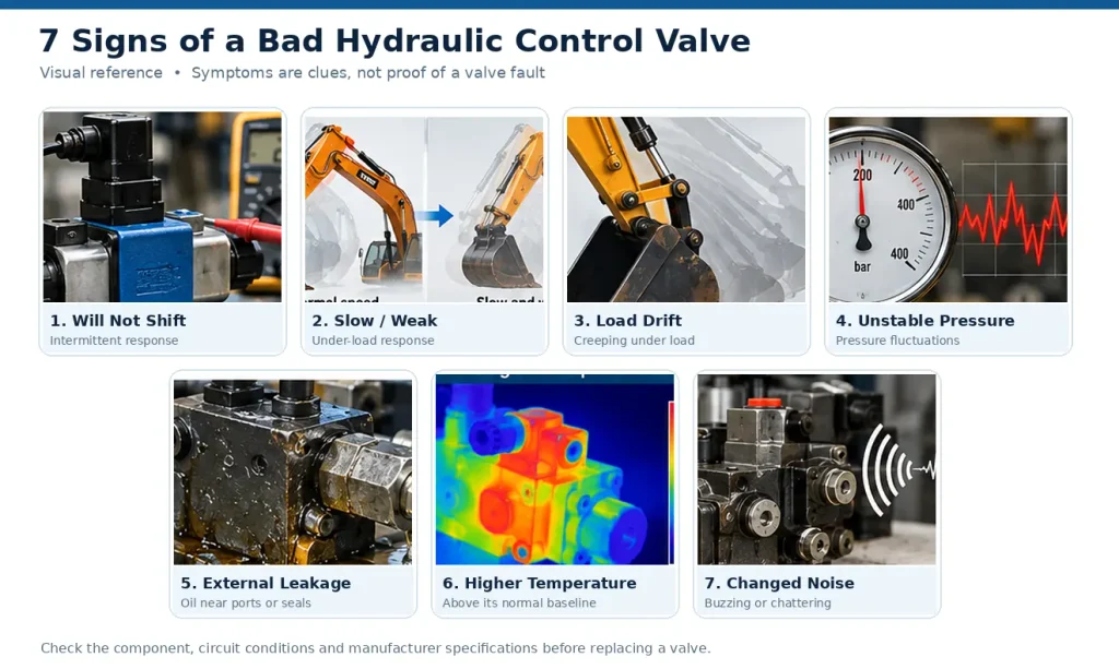
A bad hydraulic control valve shows itself in seven repeatable signs: it stops shifting reliably, actuators slow down or lose force under load, the machine drifts, pressure becomes unstable, oil appears around the body and ports, the circuit runs hotter than normal, and the noise changes. No single sign proves the valve is at fault. The repair path is consistent: confirm the symptom under controlled testing, separate an electrical or pilot fault from a mechanical one, correct the fluid conditions, then rebuild or replace. Directional Valve Manufacturer data and the machine’s service documentation set the tolerances.
Each sign follows with what it means, how to check it and how to fix it.
How to Tell If a Hydraulic Control Valve Is Bad
Match the symptom to its sign, then run the one check that separates the valve from the rest of the circuit. The table is an index, not a diagnosis.
| Sign | What the operator notices | First check | Detail |
| 1. Will not shift | No movement, or only sometimes | Voltage at the energised coil | Sign 1 |
| 2. Slow or weak actuation | Slow strokes, stalling under load | Valve pressure drop at rated flow | Sign 2 |
| 3. Drift under load | The load creeps down while held | Drift measured under load | Sign 3 |
| 4. Unstable pressure | The gauge fluctuates | Inlet and outlet pressure | Sign 4 |
| 5. External leakage | A wet film or drips at body or seals | Trace the leak to its source | Sign 5 |
| 6. Higher temperature | One circuit hotter than others | Temperature against its baseline | Sign 6 |
| 7. Changed noise | Buzzing, chattering, hissing, knocking | Locate the noise and its timing | Sign 7 |
These signs apply to control valves generally; standard directional valves tolerate more contamination than proportional or servo types, and the machine’s documentation defines the limit.
Sign 1: The Valve Will Not Shift, or Only Shifts Intermittently
A valve that will not shift has a fault in the electrical signal, the pilot supply, or the spool itself.
What happens. The actuator ignores the command, or obeys it only sometimes. A valve that works intermittently can still move, so something is stopping the shift.
Possible causes. A weak or failed coil. Voltage that collapses under load. Pilot pressure too low to shift the spool. A spool held by varnish or particles.
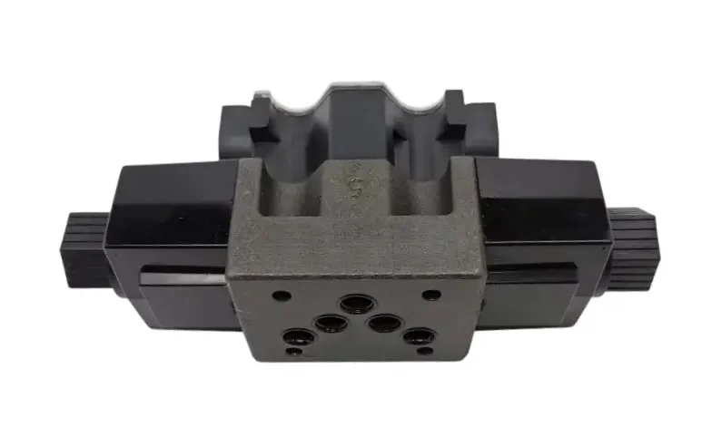
How to check. Measure voltage at the coil while energised, not at rest. Test coil resistance against the rating for that coil, which is why a Solenoid Valve Manufacturer quotes resistance and voltage together. Compare pilot pressure with specification.
How to fix it. Replace the coil or repair the wiring, and correct the pilot supply or internal drain. Where contamination caused the sticking, clean the spool and bore and fix the filtration.
Rule this out first. Loss of system pressure, a seized actuator and a missing command all look identical from the operator’s seat.
Sign 2: Actuators Move Slowly, Weakly or Lose Force Under Load
Slow, weak or stalling actuators usually mean the valve is no longer passing the flow it should, because a passage is restricted or oil is bypassing the spool.
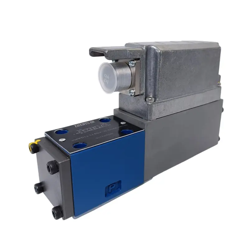
What happens. Cycle times lengthen, lifting becomes hesitant, and an unloaded stroke may complete normally while the same movement stalls under load.
Possible causes. Internal leakage across worn lands. A blocked passage or clogged strainer. A spool that no longer travels its full stroke. Inlet starvation and aeration.
How to check. Compare cycle time with the machine’s recorded baseline. Measure pressure at the valve inlet and outlet: a large drop indicates restriction, a normal drop with weak movement indicates internal leakage.
How to fix it. Clear or replace the restricted element and restore filtration. Where leakage is the cause, rebuild the valve. Repair suction connections and restore fluid level.
Rule this out first. A pump delivering insufficient flow produces this exact symptom. Measure flow upstream of the valve first.
Sign 3: The Machine Drifts or Will Not Hold a Load
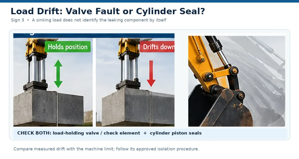
A load that creeps down while the machine is held is the classic signature of internal leakage past a valve element.
What happens. A raised boom sinks slowly, an attachment settles when the controls are released, or a clamped part loses grip over a shift.
Possible causes. Worn spool lands or a scored bore. A load-holding element that no longer seats fully. Seal wear. Pressure too low to keep it closed.
How to check. Measure drift at rest with the load applied, against the manufacturer’s limit. The element that blocks reverse flow causes it just as easily, so a pilot-operated Check Load Holding Cartridge Valve is checked alongside the main valve.
How to fix it. Replace the worn sealing element or rebuild with new spool and seal parts.
Rule this out first. A leaking cylinder seal drifts the same way. Cap the work ports to establish which component is losing the oil.
Sign 4: Pressure Is Unstable or the System Will Not Build Pressure
Pressure that fluctuates, or never reaches its setting, usually means the valve opens too early, leaks internally, or follows an unstable signal.
What happens. The gauge drifts during steady operation, spikes appear on direction changes, or the system builds pressure slowly and loses it as demand rises.
Possible causes. A relief or pressure-control element that sticks or is set low. Contamination holding a poppet off its seat. A worn spool that cannot seal. Viscosity outside the operating range.
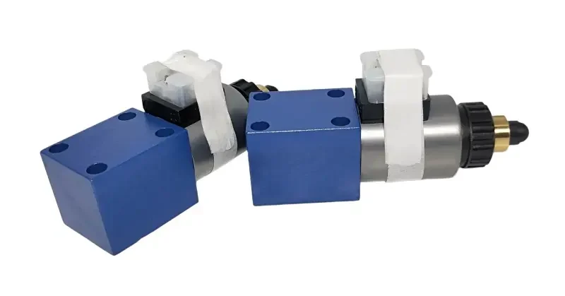
How to check. Record pressure at the valve, not at the pump line, because a reading taken in the wrong place misleads. Note whether the fault changes with temperature.
How to fix it. Clean or replace the sticking element and reset the pressure-control device. Where internal leakage is the mechanism, rebuild or replace the valve.
Rule this out first. This is the least valve-specific sign here. A relief valve set wrong and a worn pump both produce it.
Sign 5: Oil Leaks From the Valve Body, Ports or Seals
External leakage is the easiest sign to see and the easiest to postpone, and postponing it feeds the contamination that damages the valve from the inside.
What happens. A wet film or a drip appears at a seal, a fitting or the joint faces of the body. Small seepage rarely stops production, so it gets noted and left.
Possible causes. Seal degradation from heat and age. A fitting that is loose, or was overtightened and deformed the sealing surface. Cracks or porosity in the body.
How to check. Clean the area and trace the leak after a short run, because oil travels along the body. Confirm pressure including peaks sits inside the valve rating.
How to fix it. Replace the seals and address the cause, not the seal alone. Re-torque fittings to the specified value, and replace a cracked body.
Rule this out first. A leak at the valve is not always generated at the valve. Ports, hoses and manifolds share the same surfaces.
Sign 6: The Valve or Circuit Runs Hotter Than Normal
Heat is a byproduct of inefficiency, so a valve running hotter than its neighbours is turning hydraulic energy into heat through internal leakage or restriction.
What happens. Circuit temperature rises above its normal band, or one valve runs visibly hotter than others. The change is gradual and gets accepted as normal.
Possible causes. Internal leakage past the spool, sending pressurised oil to tank without doing work. Flow restriction that raises pressure drop.
How to check. Compare temperature against the machine’s own baseline, because ambient conditions and duty cycle move the number. Locate the hot area and treat its position as a pointer.
How to fix it. Correct the restriction or leakage generating the heat, then verify that reservoir, cooler and airflow meet the duty cycle.
Rule this out first. A warm valve is not automatically faulty. Ambient temperature, a blocked cooler and a high duty cycle all raise circuit temperature.
Sign 7: Noise Changes: Buzzing, Chattering, Hissing or Knocking
A change in the sound of a valve is an early indicator, provided the pattern is identified rather than simply noted, because different noises point to different mechanisms.
What happens. Buzzing at the coil, chattering while the valve shifts, a hiss from the circuit, or a knock as direction changes.
Possible causes. A coil that is energised but struggling, or the wrong supply voltage. Unstable pilot pressure or contamination, which lets the valve hunt. Aeration or cavitation, where vapour cavities collapse and erode surfaces, described in the standard reference on Cavitation.
How to check. Record when the noise occurs: at start-up, during load changes, continuously, or only at particular pressures.
How to fix it. Correct the supply where the noise is at the coil. Clean the spool area where the valve chatters. Bleed the circuit where aeration is the cause.
Rule this out first. Noise travels through the machine, so the valve is often blamed for a sound that starts at the pump.
How to Diagnose a Bad Hydraulic Control Valve
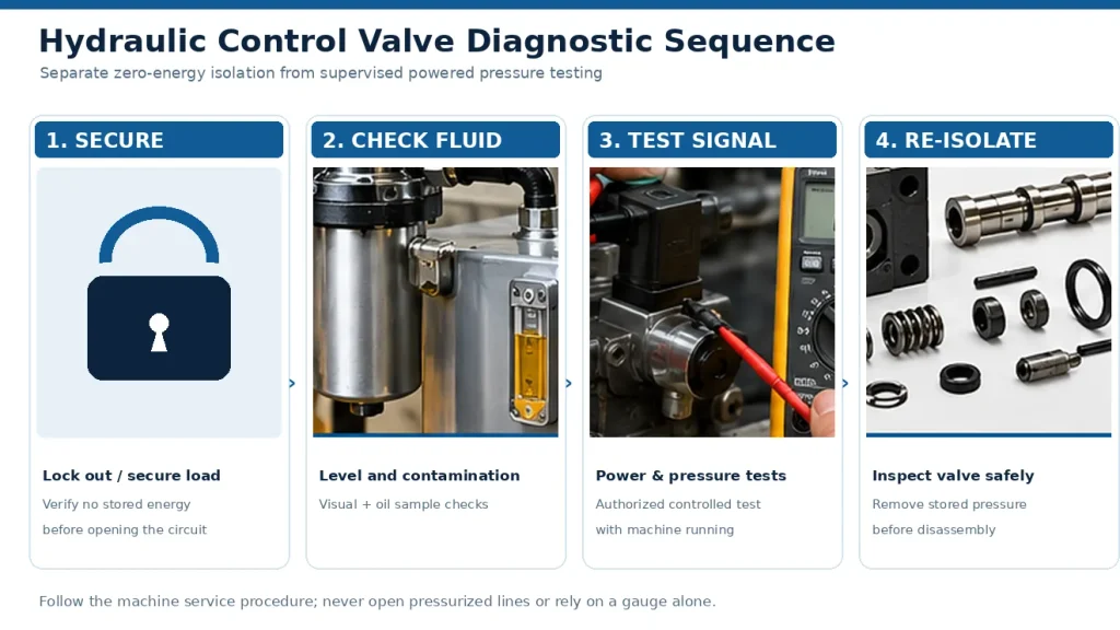
Diagnosis follows one rule: establish a safe test state before measuring anything, and treat isolation as a separate stage from the controlled powered and pressure tests.
Establish a safe test state first. Isolate and lock out the machine, release stored pressure, and secure any load that could fall. Confirm the machine cannot produce unexpected movement from an electrical or pilot signal. International standard ISO 4413 sets out the general safety requirements for hydraulic systems.
Then run controlled powered and pressure tests. Most pressure measurements need the system running rather than fully depressurised, because pressure exists only when flow meets resistance. Restore power only after the isolation checks, and follow the manufacturer’s stated procedure and permitted manual override conditions.
| Test | Measurement Point | Expected Result | Possible Fault Indication |
| Signal and coil | At the coil, energised | Voltage present, coil within rated resistance | Open circuit, poor contact, voltage collapse |
| Pilot supply | Valve pilot inlet | Stable pressure matching specification | Weak or absent pilot pressure |
| Valve pressure drop | Valve inlet and outlet | Small, consistent drop at rated flow | Large drop means restriction; normal drop with weak movement means leakage |
| Actuator behaviour | Cylinder or motor | Full stroke, consistent speed, no drift at rest | Drift means internal leakage; jerking means aeration |
- Check fluid condition and level, including contamination and water ingress.
- Measure pressure at the valve, and verify electrical supply and coil condition before any disassembly.
- Observe actuator behaviour under load and record what was measured, and where.
What Causes a Hydraulic Control Valve to Fail?
Contamination is one of the most important preventable causes of control valve failure, and it accelerates every other mechanism, wearing spool surfaces, blocking passages and holding sealing elements off their seats.
Valve clearances are measured in micrometres, and particles of comparable size abrade the spool and bore. The scratches remove sealing capacity, and the debris adds more abrasive particles. Water corrodes surfaces, air causes cavitation, and varnish can lock a spool when cold.
| Cause | Mechanism inside the valve | Sign it shows up as first |
| Particulate contamination | Abrades lands and bore, jams the spool | Sign 1 or 3 |
| Water in the fluid | Corrodes surfaces, weakens the fluid film | Sign 4 or 5 |
| Entrained air | Cavitation, weak and erratic response | Sign 2 or 7 |
| Varnish from oxidised oil | Sticky deposits fill spool clearance | Sign 1 |
Seals and springs age under heat and pressure, so a valve a few years old can drift from wear alone. Electrical faults and low pilot pressure prevent full shifting even when the valve is sound. The widely used ISO 4406 standard defines how solid particle contamination is quantified, and it underpins most machine cleanliness specifications.
When to Repair a Hydraulic Control Valve and When to Replace It
Repair is the better route when the fault is contamination, a worn seal or a failed coil and the bore is sound. Replacement becomes the better route once the bore is damaged or the same fault returns after a correct rebuild.
| Valve condition | Evidence | Recommended action |
| Sticking from contamination, bore sound | Spool frees up when cleaned | Clean, restore filtration, return to service |
| External leakage only | Leak traced to a seal or fitting | Replace seals and correct the cause |
| Coil or electrical failure | Coil open or shorted | Replace the coil |
| Internal leakage with drift | Clearances outside tolerance | Rebuild with new spool and seal parts |
| Scoring, distortion or cracks | Visible damage to bore or body | Replace the valve |
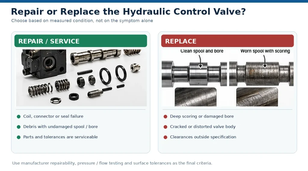
Rebuilding follows a defined sequence.
- Strip and clean the valve, assessing wear against the manufacturer’s tolerances.
- Replace every wear part removed, including seals and springs.
- Reinstate the fluid and filtration conditions that caused the damage, then test against specified pressures and flows.
For valves with fine pilot clearances, replacement is often the practical choice, which is one reason the wider Proportional Valve Manufacturer range exists.
How to Prevent Hydraulic Control Valve Failure
Prevention is almost entirely fluid and filtration discipline. Keep the fluid clean and at the right temperature, keep water and air out of it, and the valve will outlast the machine.
- Set a target cleanliness level suited to the valve model rather than a universal rule.
- Filter new oil before it enters the reservoir.
- Keep the reservoir sealed and fit a suitable breather.
- Monitor fluid temperature against a recorded baseline, and correct cooling, viscosity and airflow early.
Cleanliness targets depend on what the valve must do and how long it must last. A level that keeps a standard directional valve working may still fall short of the level that maximises service life, so confirm the model-specific requirement in the manufacturer’s specification.
FAQ
How often should a hydraulic control valve be inspected?
The interval belongs to the machine, not the valve. Sample fluid at a fixed interval, track the cleanliness reading, and inspect the valve whenever the trend moves the wrong way.
Can a sticking spool be fixed without replacing the whole valve?
Often yes, provided the bore and spool are not scored. Cleaning the element, replacing worn parts and correcting the fluid condition can return the valve to service.
Why Can Electrical Problems Mimic Hydraulic Valve Failure?
Because the hydraulic symptom is the last step in a chain. A weak coil or a damaged connector produces the same result as a sticking spool: an actuator that does not move.