Hydraulic circuits are usually specified from the pump outward, and the vane pump receives most of the attention. The rotary output end gets less scrutiny, even though the motor decides how smoothly and quietly a machine moves. Vane motors are often ruled out before the duty has been examined, even though a vane motor manufacturer can usually match displacement, speed and mounting to the duty.
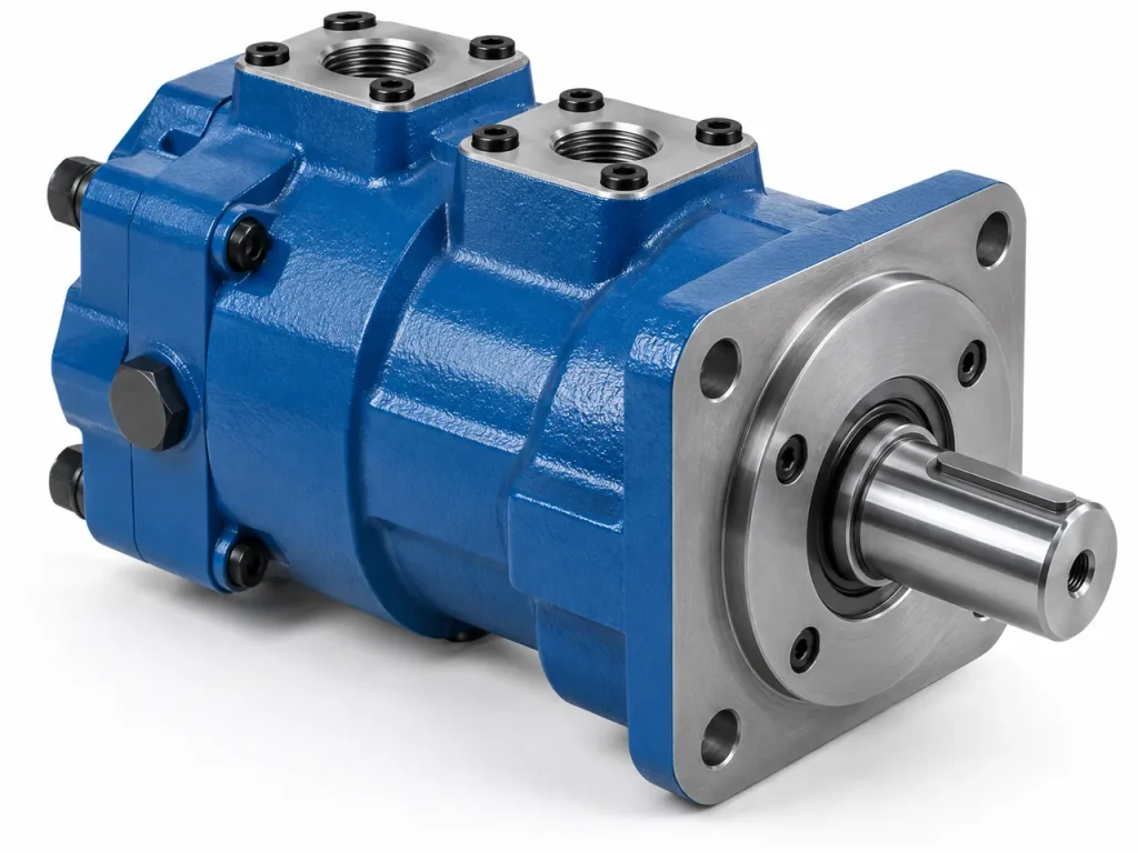
A hydraulic vane motor is a positive displacement motor that converts hydraulic pressure and flow into rotary motion through vanes sliding against a cam ring. Compared with piston motors, vane motors are commonly selected when smooth operation, low noise and compact design matter more than extreme torque density. Sizing starts from four figures: displacement, pressure rating, speed range and mounting.
The sections below cover how the vanes generate torque, which design variants exist, and where the type earns its place.
What Is a Hydraulic Vane Motor and How Does It Produce Torque?
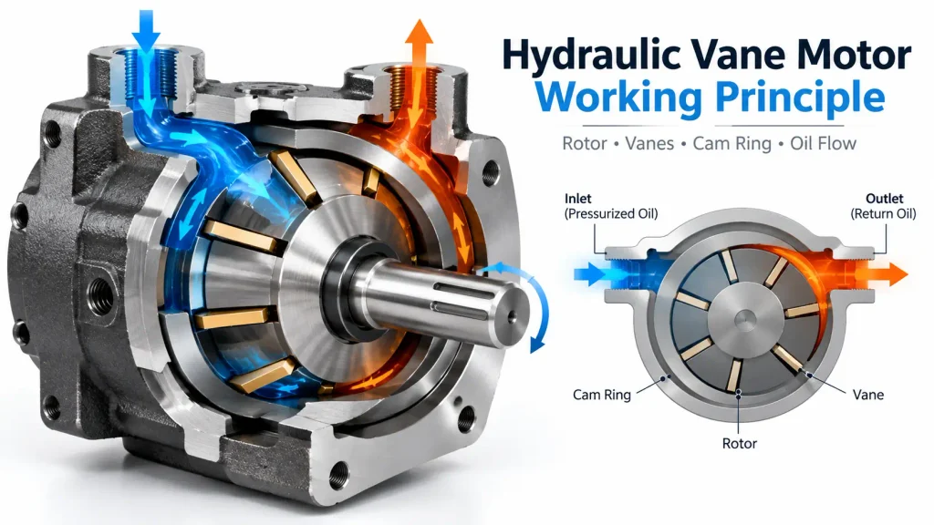
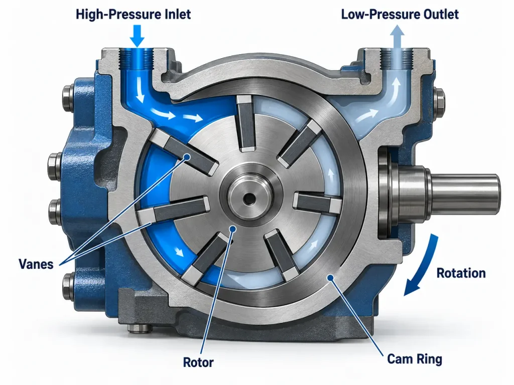
A vane motor produces torque because fluid pressure inside the cam ring is not evenly distributed. Fluid enters the chambers on one side of the rotor and pushes on the exposed vane surfaces, and the imbalance turns the rotor toward the low-pressure side. Pressure differential sets torque; flow sets speed.
Terminology matters before geometry does. A fluid power vocabulary standard fixes the terms selection depends on: displacement, the fluid volume required per revolution, and the pressure differential, which is the difference between inlet and outlet pressure rather than the gauge reading at the inlet.
The Vane as a Sealing and Torque Element
In a hydraulic motor the vane carries two jobs at once. It separates a high-pressure chamber from a low-pressure one, so it seals, and it also carries the force that turns the rotor, so it is a loaded structural member. A motor may have to produce torque from standstill, when centrifugal force is unavailable, so springs or pressure behind the vane hold it against the ring.
How the Rotor, Cam Ring and Port Timing Work Together
The rotor sits off-centre, or inside a ring machined with several lobes, so the gap between rotor and ring changes as the shaft turns. Chamber volume expands where the ports admit fluid and contracts where they release it, and port plates open each chamber to the inlet and outlet at the correct angular positions. A multi-lobe ring with opposed inlet and outlet regions largely cancels radial load, which allows continuous running at pressure without rapid bearing wear. Smoothness, however, depends on ring profile, lobe count, port timing and pressure balance rather than on vane count alone.
How a Vane Motor Differs from a Vane Pump
Both devices share a rotor, vanes, a cam ring and port plates, and the difference lies in the duty. A motor must accept flow in either direction, produce torque from standstill against a load, and tolerate case pressure from a restricted return line, which a pump is not built to do.
Motor porting is therefore arranged for both directions, and the housing needs a drain that keeps return-line pressure away from the shaft seal. The pump-side classification of the same hardware is set out under What Is a Vane Pump.
Vane Motor Designs: Fixed Displacement, Variable and Cartridge Types
Vane motors are classified along three engineering lines rather than by name: whether the radial load is pressure balanced, whether displacement can change while running, and whether the working group is a replaceable cartridge. A balanced ring makes the type usable at continuous pressure, while the other two decide how it is controlled and how it is maintained.
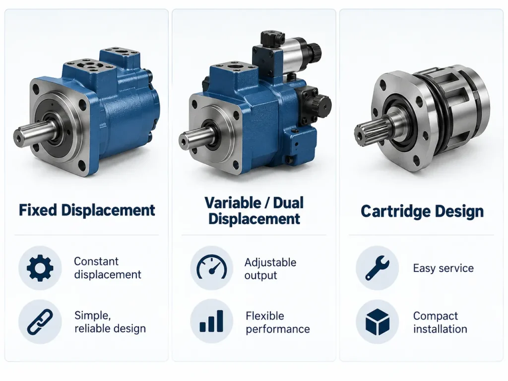
The three lines combine freely: a fixed-displacement, pressure-balanced motor with a cartridge group covers most industrial and mobile duties.
Pressure-Balanced Designs
In a balanced vane motor the cam ring carries two or more opposed sets of inlet and outlet ports, so pressure acts on opposite sides of the rotor and the radial forces largely cancel. That is why the family can run continuously at pressure with acceptable bearing life. Production motors commonly use ten or twelve vanes in a cartridge group and are quoted for intermittent pressure above the continuous figure, assuming short bursts followed by a lighter load.
Fixed Displacement Designs
A fixed displacement motor delivers a constant volume per revolution, so speed follows the flow supplied to it and torque follows the pressure differential. There is no internal adjustment to consider, which is why the arrangement dominates drives whose duty is known in advance. Because several displacements can share one frame size, a builder can cover a range of duties with a common flange and a common spare part family. The fixed displacement hydraulic vane motor range follows that pattern: one frame, several displacements, the same mounting.
Variable and Dual Displacement Designs
A variable vane motor moves the cam ring, or changes its eccentricity, so displacement changes while it runs, and one unit can deliver more torque at low speed or less at high speed from the same supply. Dual displacement designs switch between two preset values through a control piston.
Two cautions apply. Switching ratios are a property of the design, and values around three to one and four to one are common rather than universal, so no general rule says that a change of displacement doubles speed as it halves torque.
Cartridge Construction and Service Economics
Many vane motors are built around a cartridge: rotor, vanes, cam ring and port plates assembled as one unit that can be withdrawn without disturbing the housing, shaft or mounting. A major repair therefore becomes a component swap rather than a rebuild, and where downtime costs more than parts, that often decides the choice.
What Are the Benefits of a Hydraulic Vane Motor?
The advantages of a vane motor follow directly from even pressure distribution and continuous vane contact with the ring. Smooth torque, quiet running, fast response and compact size are consequences of one mechanism rather than separate features, and each can be checked against a measured figure.
Smooth, Low-Pulsation Torque
Gear meshing produces a torque variation with every tooth engagement, and piston designs produce one with every piston stroke. A vane motor has no comparable discrete event, because several vanes stay in contact with the ring and the chambers filling and emptying overlap in phase. In a balanced multi-vane cartridge a peak-to-peak fluctuation within roughly one and a half percent of mean torque is achievable, so measured ripple rather than vane count is the figure to request.
Efficient Operation in Continuous Duty
Vane motors return good overall efficiency, commonly in the region of eighty-five to ninety percent in a well-matched installation, and they hold it across a wide speed band rather than at a single point. That matters more than a peak figure, because most drives spend their life away from their best operating point, and a cooling fan drive may sit at constant pressure for a whole shift without the losses climbing.
Quiet Running and Low Vibration
Noise comes largely from pressure pulsation and from excitation of the surrounding structure. Because a balanced motor spreads the filling and emptying of chambers across rotation rather than concentrating it, the ripple it feeds into the circuit is small, and the low radial bearing load it carries reduces the vibration transmitted into the frame. On equipment used near operators for long periods, such as a mobile cooling fan, the difference is both audible and measurable.
Compact Package and Fast Response
The working parts sit in one plane between the end covers, so a motor of a given displacement occupies less axial length than many alternatives, and the rotor group carries little inertia. Speed changes therefore follow flow changes with little lag, which suits drives that reverse frequently or follow a control signal, such as indexing mechanisms and fan drives that track engine load.
Cartridge Serviceability
A cartridge group can be exchanged as a unit, so the wearing parts are renewed together as a matched set, without disturbing the housing or the shaft alignment. For a machine that cannot afford a long stop, that turns a major repair into a planned component swap.
| Performance behaviour | What it means on the machine | How to verify it |
| Low torque ripple | Smoother feeding and positioning | Ask for measured ripple at working pressure |
| Balanced radial load | Longer bearing life, less vibration | Confirm a pressure-balanced ring, not single-lobe |
| High speed capability | Fan and roller drives at pump-side speeds | Compare maximum speed with available flow |
| Low rotor inertia | Quicker response to flow changes | Compare inertia where a control loop is used |
| Cartridge layout | Wearing parts renewed as a set | Confirm a replaceable cartridge group |
| Continuous duty efficiency | Lower heat input per hour | Compare efficiency at the actual duty point |
Where Hydraulic Vane Motors Are Used
Vane motors earn their place in selected applications rather than in every rotary duty. They suit reasonably clean circuits, continuous or high-speed operation, and duties where smoothness and noise matter. Where a duty needs extreme torque at very low speed, or where the fluid will be heavily contaminated, another motor type is normally the more common selection.
The list below is characteristic rather than exclusive, since most of these duties can be served by more than one motor type.
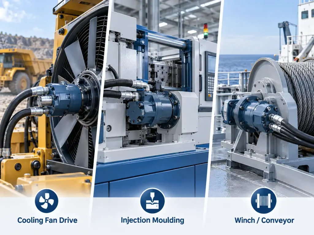
Mobile Cooling and Fan Drives
A cooling fan is close to an ideal duty. It needs continuous rotation at high speed, the load is light and nearly constant, and the fan often has to modulate with engine load or coolant temperature. Low inertia and quick response suit that modulation, and quiet running matters because the fan sits on a machine that must meet noise limits.
A vane motor is not a high-torque device at very low speed, so a fan drive suits it better than a winch or track drive. Balanced designs are quoted for several thousand revolutions per minute and for intermittent pressure above the continuous figure, which covers the transient when the fan is commanded from rest. The hydraulic vane motor range built for fan drives follows exactly that assumption.
Injection Moulding, Machine Tools and Presses
On an injection moulding machine the screw must rotate smoothly under a load that changes with material and melt state, and variable displacement is often used so one unit covers plasticising and recovery. Machine tool rotary tables and tool changers need precise low-speed positioning without stick-slip. Presses use motors on auxiliary functions, where controllability matters more than power.
Marine Winches, Conveyors and Roller Drives
Deck machinery and trawler winches often run in damp, salt-laden air, where seal selection and corrosion-compatible materials matter as much as the hydraulic rating. Conveyor and feeder drives in bulk handling are steady duties where smooth torque avoids spillage, and roller drives on compaction equipment need low-speed stability without jitter.
One caveat applies in every case. Holding a suspended load is not a motor function, so a load left hanging over a hatch needs a brake or a load-holding valve acting on the circuit, and the motor supplies driving torque only.
Where a Vane Motor Is Usually Not the First Choice
Two duties are worth naming because they are where specifications most often go wrong. On excavators, swing and travel are more commonly driven by an axial piston motor, usually through a planetary reduction, because the duty needs high pressure, a wide speed range and a closed circuit rather than smoothness. Heavy hoisting more often uses a radial piston motor, which produces very high torque without a gearbox.
The second case is contamination. Dirty fluid shortens the life of any close-clearance component, and vane tips and port faces are among the more sensitive surfaces. Where filtration cannot be maintained, a gear motor or a rugged piston design is usually the more forgiving choice. Neither statement excludes the type; it means the compromise should be made deliberately.
What Limits a Vane Motor, and How Do You Select One?
The limits of a vane motor trace back to one fact: the vanes have to seal against the ring, so everything depends on clearance and on a fluid film being present. Pressure, speed, cleanliness, viscosity and drain arrangement appear as separate constraints on a datasheet, but they are the same constraint expressed five ways.
A selection is not complete when torque and speed are satisfied, because the circuit also has to deliver clean fluid at the right viscosity and give the case drain somewhere to go.
Pressure, Speed and Low-Speed Torque Limits
Continuous and intermittent pressure are separate ratings, and the difference is not a marketing margin. A continuous figure assumes the motor will hold that pressure for the working life of the machine, while an intermittent figure assumes brief durations followed by a return to a lighter load. Speed has two ends: the upper end is set by vane tip velocity and bearing life, and the lower end by internal leakage, which becomes a larger fraction of the useful flow as speed falls. A minimum stable speed exists for each design and should come from measurement rather than a catalogue range.
Cleanliness, Viscosity and Case Drain Requirements
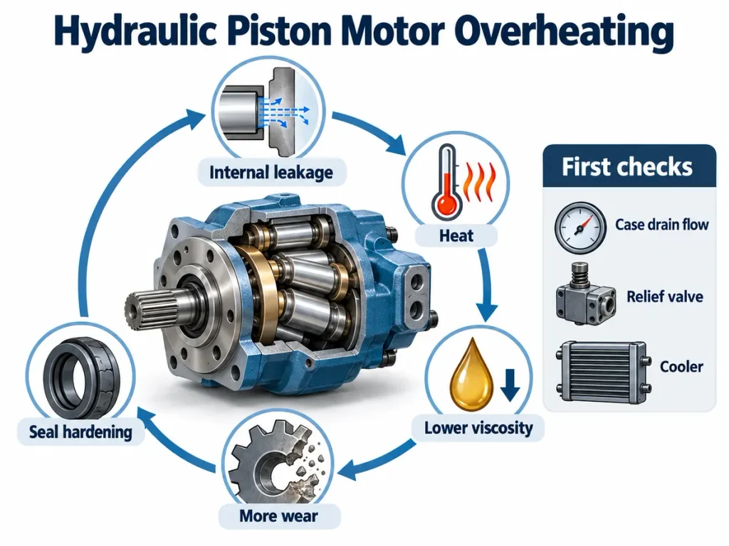
Vane tips and port faces are among the first surfaces to suffer from dirty oil, and the failure is gradual: leakage past the tips rises, torque falls at low speed first and at higher speed later, and case drain flow increases. Filtration should therefore be specified to a stated cleanliness class rather than to a nominal micron rating, and the class should be written into the maintenance procedure.
Viscosity decides whether the film survives at working temperature, and the case drain decides whether the shaft seal survives at all, because above a stated case pressure the seal is the component that fails.
Mounting, Shaft, Rotation and Seal Variables
The mechanical interface decides as much as the hydraulic one. Flange pattern and pilot diameter set whether the motor fits, shaft type and key size set whether it can be coupled, and rotation direction has to match the porting, since a design intended for one direction may not be balanced for the other. Where both directions are needed, that belongs in the enquiry, not a later correction.
Seal material follows the fluid and the environment. The General rules and safety requirements for hydraulic systems and components also cover installation and adjustment as part of the machine design, which is a workable frame for the checklist below.
| Selection factor | Why it matters | Check before purchase |
| Displacement | Sets the flow-to-speed and pressure-to-torque ratio | Confirm the figure and unit, ml/rev or cc/rev |
| Pressure rating | Continuous and intermittent limits wear differently | Specify against the continuous figure for steady duty |
| Speed range | Top limited by tip speed, bottom by leakage | Ask for the minimum stable speed from test data |
| Fluid cleanliness class | Tips and port faces wear with particle count | Fix a class and a sampling interval |
| Viscosity window | Sealing film and chamber filling must both hold | Compare with the oil actually used in the field |
| Drain and mounting | Case pressure limits seal life, flange sets fit | Size the drain for end-of-life leakage |
Where a standard unit cannot be fitted into an existing envelope, changing the mounting pattern or the displacement is usually cheaper than redesigning the machine, and a custom hydraulic motor built to the required flange, shaft and displacement serves that purpose.
Frequently Asked Questions
What is the difference between a vane motor and a piston motor?
A piston motor tolerates higher pressure and delivers more torque from a given size, because its pistons seal against their bores positively rather than through sliding contact with a ring. A vane motor counters with smoothness, lower noise and quicker response. Duties dominated by extreme low-speed torque point to a piston design; those dominated by continuous, smooth or quiet rotation point to a vane motor.
Can a hydraulic vane motor be reversed under load?
Usually yes, and more readily than most types, because a balanced design produces useful torque in either direction. Three conditions have to be met. The porting, and any built-in rotary valve, must be configured for the direction required; the drain arrangement must stay within its case pressure limit when the outlet changes role; and the seal must suit both directions. An anti-cavitation provision is also needed so the motor does not draw vacuum while the load drives it.
Why does a vane motor lose torque at low speed?
Internal leakage. At high speed the leakage past the vane tips and port faces is a small fraction of the flow passing through the motor, and at low speed the same volume becomes a large fraction, so less pressure differential remains to make torque. Friction between the vane tips and the ring adds a further loss as the fluid film thins. The practical answer is a minimum stable speed quoted for the specific unit.
How long does a hydraulic vane motor last?
Service life is set by wear on three parts, the vanes, the cam ring and the port faces, and it varies with pressure, speed, duty cycle and oil cleanliness more than with the design itself. A motor held at moderate continuous pressure with clean fluid can run for many thousands of hours, while one run at its intermittent limit with marginal filtration can need a cartridge in a fraction of that. The way to establish your own interval is to track case drain flow, which rises as wear progresses.
Does the number of vanes determine how smoothly a vane motor runs?
No, and treating the count as a specification is a common mistake. Smoothness depends on the ring profile and its lobe count, the port timing and the degree of pressure balance, so a well-designed ten-vane and twelve-vane cartridge can differ more because of those factors than because of the count. Ask for a measured torque ripple figure at the working pressure instead.