Hydraulic valve failure rarely appears as a single dramatic event. Because a hydraulic valve decides where fluid travels, how fast it moves and at what pressure it arrives, the wider hydraulic machinery depends on that regulation, and a small loss of valve performance spreads through the entire circuit. It usually appears first as a cylinder that moves more slowly, a gauge that no longer holds steady, or a machine that drifts out of position under load. A Hydraulic Valve Manufacturer supplying mobile and industrial circuits meets the same root causes repeatedly, and most are preventable once recognised.
The most common cause of hydraulic valve failure is contaminated fluid, but it is far from the only one. Particles, water and air attack fine internal clearances and turn ordinary wear into rapid wear, while degraded seals, fatigued springs, varnish deposits, electrical faults and incorrect settings cause failures of their own.
This article follows those causes of hydraulic valve failure in the order a maintenance team meets them, then explains how to diagnose a suspected fault and how to prevent hydraulic valve failure from returning.
Signs of a Failing Hydraulic Valve
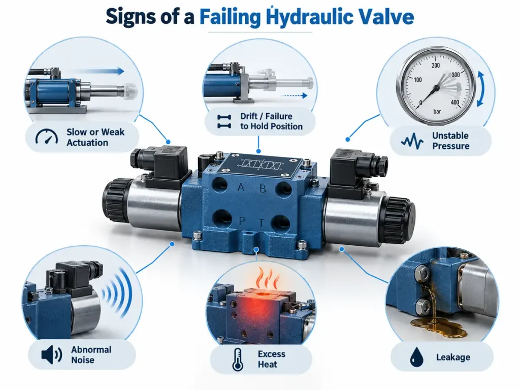
A failing hydraulic valve normally degrades before it stops working, but the warning signs belong to the system as much as to the valve. Slow or weak actuation, drift, unstable pressure, abnormal noise, excess heat and leakage can indicate a hydraulic valve fault, and each can equally come from the pump, the actuator, the filtration or the electrical supply.
Performance Symptoms
A valve that no longer opens fully reduces the flow reaching the actuator, so a motor or cylinder becomes slow and weak under load. A spool that leaks internally lets fluid bypass the working port, producing drift and loss of holding force. Because sluggish movement can also come from a restricted filter or a worn pump, and drift under load from leakage past the piston seal, recognising hydraulic valve failure symptoms means testing candidate components in order rather than replacing the most visible one.
Physical and Sensory Warning Signs
Noise usually has a recognisable character. A hiss suggests fluid forcing through a restriction or past an eroded spool edge, a whistle or gurgle points to air in the fluid, and knocking suggests a spool that cannot settle because a spring is weak. Internal leakage converts hydraulic power directly into heat, so a valve that has begun to bypass runs warmer than its neighbours, and fluid that has turned dark, cloudy or burnt smelling confirms overheating, water ingress or oxidation.
| Symptom | Possible cause | First check to run |
| Slow or weak actuation under load | Spool leakage, loss of pump output, flow setting too low | Compare pump flow and pressure against specification |
| Drift, or failure to hold position | Leakage past a valve or past the cylinder piston seal | Isolate the actuator and repeat the drift test |
| Pressure unstable or outside specification | Worn spool or seat, blocked pilot orifice, incorrect relief setting | Verify the gauge, then the relief valve setting |
Sticking appears most often on directional and pressure-control valves, whose spools shift millions of times in service. When sticking begins, a Directional Valve Manufacturer examines fluid cleanliness and bore wear first.
The Most Common Cause of Hydraulic Valve Failure: Contaminated Fluid
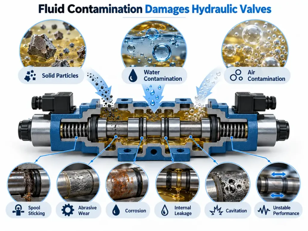
Fluid contamination is one of the leading preventable causes of hydraulic valve failure. Solid particles cause spool sticking, abrasive wear and internal leakage, while water and air cause corrosion and unstable performance. Industry studies commonly attribute the majority of hydraulic system failures, often quoted between 70 and 90 percent, to contaminated oil.
How Solid Particles Damage Valve Spools and Bores
The clearance between a spool and its bore is measured in microns, and in precision valves it can be smaller than the particles that reach it. The unaided eye stops resolving particles at roughly 40 microns, so fluid that looks clean can still carry particles large enough to cause damage.
When a particle is larger than the clearance it must pass, it is dragged between two moving surfaces and cuts a groove, a mechanism known as three-body abrasion. The groove removes the finish the land relies on to seal, fluid starts to bypass the working port, and debris from the first scratch abrades the next surface. Servo and proportional valves suffer first, because particles of a few microns can block a pilot passage.
Water and Air Contamination
Water enters through condensation, a damaged breather, a leaking heat exchanger, or humid air drawn into the reservoir. It reduces the lubricating film between moving surfaces, promotes corrosion on spool lands and seats, and degrades the additive package.
Air causes a different fault depending on how it is present. Entrained air reduces bulk stiffness, so the circuit responds in a spongy, imprecise way, while vapour released at low pressure produces cavitation, in which collapsing bubbles erode metal surfaces. Both also raise fluid temperature, accelerating the seal and varnish problems described later.
Cleanliness Requirements for Different Hydraulic Valves
The ISO 4406:2021 standard defines the code used to report solid particle contamination, expressed as three numbers representing counts above 4, 6 and 14 microns per millilitre, with lower numbers meaning cleaner fluid (ISO 4406). The code states cleanliness consistently, but it does not itself impose one mandatory target on every valve. The target for a circuit is set by its most contamination-sensitive valve, using the figures the valve maker publishes.
| Valve type | Contamination sensitivity | Typical cleanliness recommendation |
| Servo valve | Very high, pilot orifices can be blocked by particles of a few microns | Among the cleanest targets in the circuit, commonly 16/14/11 or cleaner |
| Proportional valve | High, small particles change spool friction and control accuracy | Cleaner than conventional valves, commonly around 17/15/12 |
| Solenoid directional valve | Moderate, tighter than a manual valve but more tolerant than a proportional valve | Commonly around 18/16/13 |
| Pressure control valve | Moderate, pilot orifices and seats sensitive to blockage and erosion | Commonly around 18/16/13 |
In a circuit that mixes valve types the most sensitive valve decides the filtration target, which is why a Proportional Valve Manufacturer usually specifies a tighter band than the pump in the same circuit requires.
Mechanical Wear, Seal Damage, and Varnish Deposits
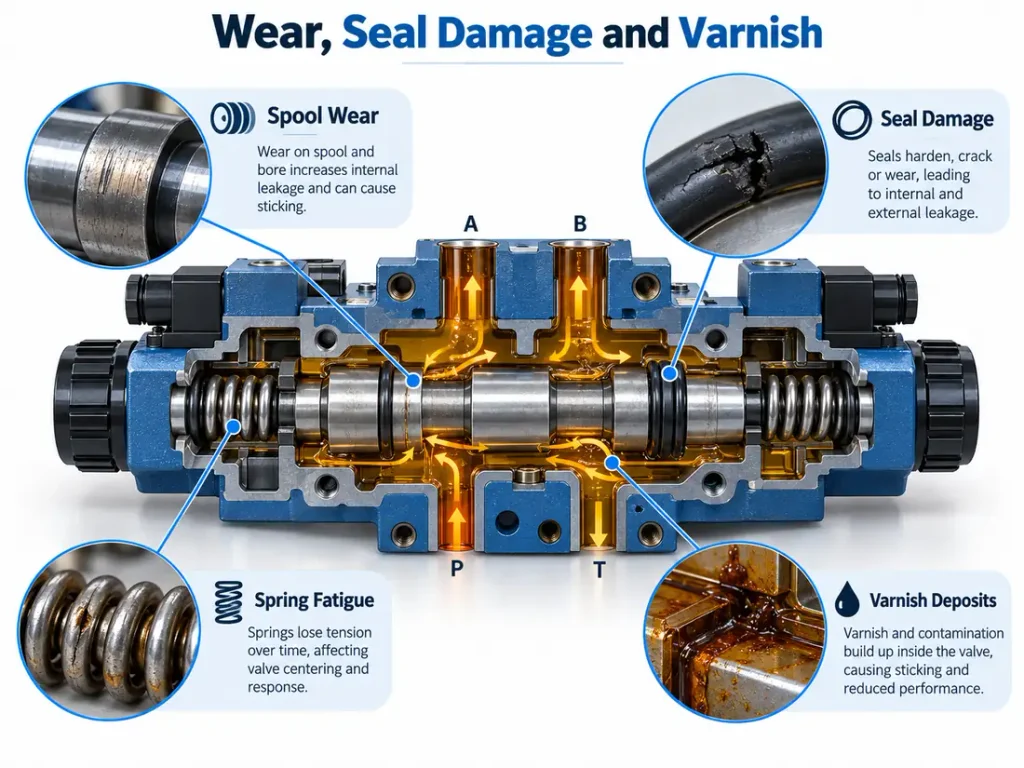
Mechanical and chemical degradation cause hydraulic valve failure alongside contamination. Seals harden and lose elasticity, springs fatigue and drift from their settings, spool and bore surfaces wear or erode, and oil oxidation leaves sticky deposits that can lock a spool in place.
Seal, O-Ring, and Spring Degradation
Elastomer seals are designed to stay flexible for years, but heat, pressure cycling and prolonged fluid contact harden and embrittle them, and a seal that can no longer follow the movement it accommodates begins to leak. Installation and fluid selection decide how fast that happens, since an incompatible seal package will swell, soften or shrink. Springs fail more quietly, because a return spring compressed for its whole service life deforms or fractures and the valve opens at a pressure that drifts from its setting.
Spool Wear, Erosion, and Fatigue
Spools in high-cycle machinery can be actuated tens of thousands of times a day, and the sealing surfaces on the land and in the bore absorb that repetition. Clearance grows, internal leakage rises and the valve loses its ability to hold pressure against a load. Directional valves commonly endure a few million cycles before a rebuild, whereas proportional and servo valves usually need attention sooner.
Varnish Deposits and Sticking Valves
Varnish forms when oil degrades. Thermal stress and oxidation break down the base oil and the additive package, and the products polymerise into sticky, insoluble compounds that filtration cannot remove because they are dissolved rather than suspended in the fluid. The deposits collect around spool ends and control chambers, narrowing the clearance the spool needs. The valve then works while the oil is warm and refuses to shift after a cold start.
Electrical, Solenoid, and Pilot-Control Failures
A hydraulically sound valve can still fail electrically. A coil that loses continuity, a supply voltage outside the coil rating, a corroded connector or a damaged pilot stage stops a valve shifting even though its spool and bore are unworn.
Coil, Voltage, and Wiring Problems
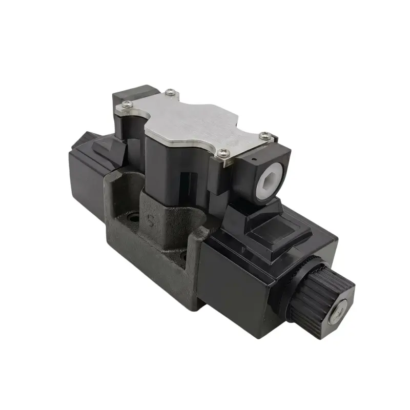
A solenoid coil produces a defined force at a defined voltage, so anything that reduces the current through it reduces the force available for shifting. Low supply voltage, a voltage drop across a long cable run, or a coil rated for a different supply all produce weak, erratic or delayed shifting. Moisture, corroded pins or a partly seated plug produce intermittent faults that resist every hydraulic explanation, and a Solenoid Valve Manufacturer publishes both the coil rating and the fluid temperature limit the seal package can survive.
Pilot Pressure and Feedback-Signal Problems
Pilot-operated valves need a minimum pilot pressure to move the main spool, and any shortfall produces incomplete or absent shifting. A blocked pilot orifice, a saturated pilot filter or an internal leakage path that steals pilot flow will each drop pilot pressure below that threshold. Proportional and servo valves add a second layer of sensitivity, because their output is a continuous function of an electrical command, so small signal errors become lost accuracy and a faulty feedback transducer makes a mechanically perfect valve hold the wrong position.
Installation and Operating Conditions That Damage Hydraulic Valves
Many valve failures are introduced rather than worn in. Incorrect pressure settings, over-tightened fittings, the wrong mounting orientation, contamination admitted during maintenance, and sustained overheating or aeration all shorten valve life and accelerate the mechanisms described above.
Incorrect Settings and Assembly Errors
Setting a relief valve above its rated value is among the most damaging common mistakes, because the valve then opens far more often than intended and every opening applies an impact load to the cone and seat. Over-tightening a fitting can crack a casting or distort an internal bore, and a distorted bore turns a freely moving spool into a sticking one. Some valves also require a specific mounting orientation for internal drainage, and installing them the other way round lets contaminants collect.
Overheating, Aeration, and Fluid Viscosity
Contamination admitted during maintenance deserves separate mention, because much of the debris that eventually causes a valve to fail enters while the system is being serviced, and oil taken from a drum is often dirtier than the cleanliness class the circuit requires. Heat accelerates every mechanism at once, oxidising the oil, hardening seals, reducing viscosity and increasing internal leakage, while aeration appears as noise and spongy response and cavitation erodes metal surfaces directly (cavitation). Fluid that is too thick will not fill the pump properly, and fluid that is too thin loses its load-carrying film.
How to Troubleshoot a Suspected Hydraulic Valve Failure
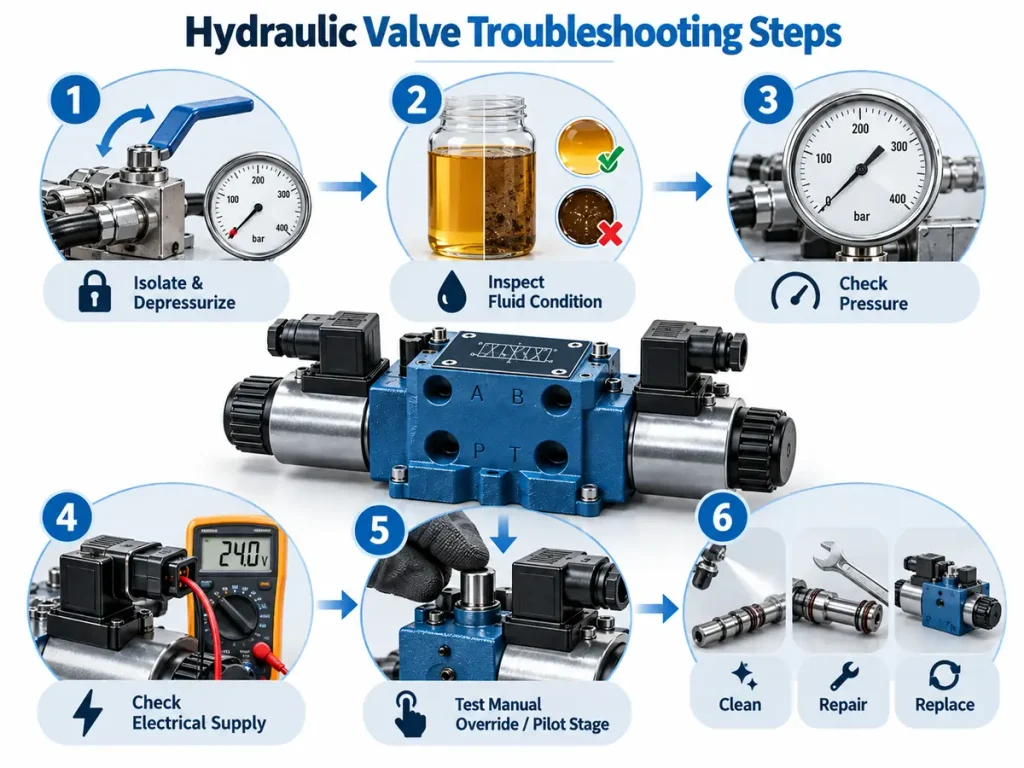
Hydraulic valve troubleshooting should always begin by isolating and depressurising the circuit, never by removing the valve. Work from the least invasive check to the most invasive: fluid condition first, then system pressure, then the electrical supply, and only then the valve itself.
Safety comes first. Relieve system pressure, isolate and lock out the power source, and allow hot components to cool, because hydraulic fluid under pressure can penetrate skin and cause serious injury.
Check Fluid, Pressure, and Electrical Supply First
- Isolate the machine, depressurise the circuit and confirm zero pressure before opening anything.
- Check fluid level and appearance at the sight glass for cloudiness, darkening or a burnt smell.
- Take an oil sample for particle count, water content and viscosity rather than judging by eye.
- Install a calibrated gauge at the valve inlet and compare with specification, treating a swing of over ten percent as an internal fault.
- Measure supply voltage at the connector and check coil continuity against the maker’s data.
- Inspect the return filter for bypass and the breather for saturation or damage.
Determine Whether the Valve or Another Component Is at Fault
The manual override test is the most informative single check available. If the valve shifts freely by hand but not on command, the spool is not jammed and the fault lies in the pilot stage, the electronics or the supply, while a spool that cannot be moved by hand points to mechanical sticking or a distorted bore. Drift needs localising rather than assuming, since isolating the actuator shows whether fluid escapes past the valve or past the piston seal.
Confirm too that the pump still delivers the required flow and pressure, because a pump that has lost output makes every valve downstream look faulty, and the principles in How Do Hydraulic Pumps Work separate a supply problem from a valve problem.
Decide Whether to Clean, Repair, or Replace the Valve
The decision follows from what the inspection found, and a valve should only be repaired once the cause of the fault has been removed.
| Observed condition | Recommended action | Reason |
| Contamination or a blocked orifice with no surface damage | Clean the valve, flush the circuit and refit with correct filtration | The fault is reversible and the valve hardware is intact |
| Light spool scoring with leakage inside a tolerable band | Repair with a seal and spool kit where the maker supplies one | Function is restored at lower cost than replacement |
| Deep scoring, eroded lands or a damaged bore | Replace the valve | Clearances and sealing surfaces can no longer be restored |
| Cracked body, distorted casting or stripped ports | Replace the valve and correct the installation | Structural damage is not repairable and indicates an assembly fault |
Repairing a valve without removing the cause guarantees a repeat failure.
How to Prevent Hydraulic Valve Failure
Preventing hydraulic valve failure depends far less on the valve than on the system around it. Clean fluid, controlled temperature, correct settings and an inspection routine matched to the duty of the machine remove most of the causes described above before they begin, and controlling fluid cleanliness is the highest-value action of all.
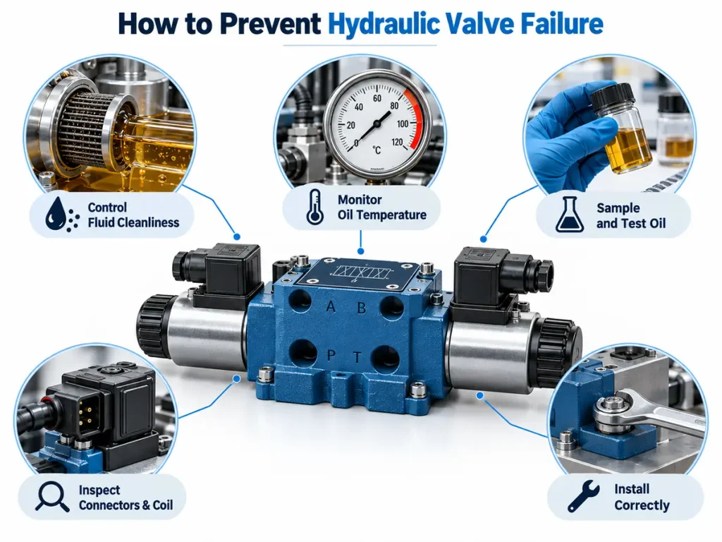
Control Hydraulic Fluid Cleanliness
Filtration begins before the fluid reaches the circuit, because new oil should be filtered as it is transferred rather than poured through a funnel. The element should be selected by rating and beta ratio at the particle sizes that matter for the most sensitive valve in the circuit, and changed on differential pressure or on a schedule derived from oil analysis. A sealed reservoir with a correct breather prevents dirt and water entering between services.
Manage Oil Temperature and Fluid Condition
Coolers should be cleaned and airflow around them kept clear, because a cooler that has clogged silently raises fluid temperature and accelerates every degradation mechanism in the circuit. Temperature should be monitored against the band the components were selected for, and any sustained upward drift treated as a fault. Oil condition should be confirmed by testing rather than appearance.
Follow a Preventive Inspection Routine
The scope and frequency of valve inspection should be set by the duty of the machine, the requirements of the component maker, the consequence of an unexpected failure and the maintenance history of the asset, because a fixed calendar either wastes effort on low-consequence equipment or leaves critical equipment under-inspected. A practical routine covers fluid level and appearance, filter indicators, breather condition, leakage at fittings and seals, valve body temperature, changes in noise, and coil and connector condition.
Select and Install Valves for the Application
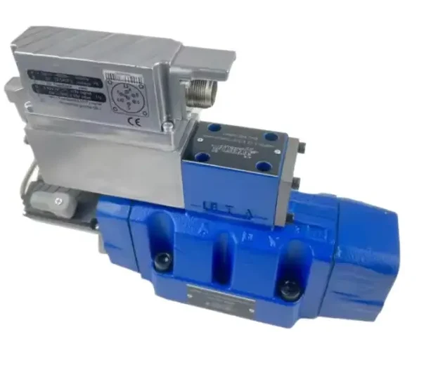
Selection begins with matching the rated pressure and flow to the duty with a sensible margin, since a valve run close to its flow limit erodes internally while one oversized for the flow it actually sees loses control resolution and generates heat. Installation decides how much of that design life is realised, so mounting orientation, tightening torque, seal lubrication and cleanliness during assembly all matter, and a Custom Hydraulic Valve lets the specification follow the application where a standard unit does not match the duty.
| Failure cause | Prevention action | Monitoring method |
| Particulate contamination | Filter fluid on fill and continuously in service | Scheduled particle counts against the target cleanliness code |
| Water contamination | Sealed storage, correct breather, desiccant breather in humid plants | Water content measured on each oil sample |
| Overheating | Maintain coolers, clear airflow, keep fluid within the design band | Fluid temperature logging and periodic thermal checks |
| Electrical and coil faults | Correct voltage and coil rating, sealed connectors, strain relief | Coil resistance and supply voltage checks |
Frequently Asked Questions
How long should a hydraulic valve last?
Directional valves commonly survive a few million operating cycles before a rebuild, while proportional and servo valves usually need attention sooner because their tolerances and pilot stages are more delicate. Life depends far more on fluid cleanliness, temperature and maintenance practice than on the valve design.
Can a contaminated hydraulic valve be cleaned and reused?
Often it can, provided the contamination has not caused permanent surface damage. Cleaning the valve, flushing the circuit and correcting the filtration will normally restore full function. If the spool or bore is scored, cleaning will not restore the clearances that sealing depends on and the valve should be replaced. Either way the filtration fault must be corrected, or the replacement fails in the same way.
How do you tell whether the problem is in the valve or in the pump?
The distinction usually appears in the pattern of the symptom. A pump that has lost output affects every circuit it supplies, so several functions weaken at once and pressure runs low. A valve fault is normally confined to one function and persists even when pump flow and pressure are confirmed to be correct.
Why does a hydraulic valve keep sticking?
Repeated sticking almost always means the cause was never removed. The most frequent reasons are fluid cleanliness outside the tolerance of that valve, varnish from oxidised oil, a bore distorted by an over-tightened fitting, or a fluid incompatible with the seal package. Cleaning the spool without correcting the underlying condition guarantees the same fault again.