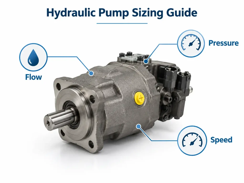
Hydraulic Pumps work by converting mechanical energy from an engine, electric motor, or other prime mover into hydraulic flow. Their internal mechanism repeatedly expands and contracts sealed chambers to draw fluid from a reservoir and discharge it into the system. Pressure develops when that flow encounters resistance from a load, valve, actuator, or pipe restriction.
The following sections explain this operating cycle step by step, compare the main pump types, and cover selection, limitations, failure causes, and service life.
What Is a Hydraulic Pump and What Does It Do?
A hydraulic pump is an energy-conversion device that supplies fluid flow to a hydraulic circuit. It receives mechanical input at its shaft and transfers that energy to the hydraulic fluid, enabling the system to move, lift, clamp, rotate, or press a load.
The Main Components Around the Pump
A typical hydraulic circuit includes:
- A prime mover that rotates the pump shaft
- A reservoir that stores and conditions the fluid
- An inlet line that supplies fluid to the pump
- A pressure line that carries flow away from the pump
- Control valves that regulate direction, pressure, and flow
- A relief valve or another pressure-limiting device
- A cylinder or motor that converts hydraulic energy into motion
- A return path that carries fluid back to the reservoir or pump inlet
- Filters that control solid and other contaminants
Every component affects the pump. A restricted inlet can cause cavitation, an incorrectly adjusted valve can create excess heat, and an undersized return line can increase backpressure.
How Do Hydraulic Pumps Work Step by Step?
Hydraulic Pumps operate through a repeating positive-displacement cycle: the pump is driven, an internal chamber expands, fluid enters and becomes trapped, the chamber moves toward the outlet, and its volume decreases or reconnects with the discharge port so that fluid is forced into the circuit.
The precise movement varies among gear, vane, and piston designs, but the underlying process is similar. Official technical guidance on hydraulic pump classifications and pumping mechanisms describes the same fundamental use of gears, vanes, gerotors, and pistons to move fluid.
Step 1: The Prime Mover Drives the Pump
An electric motor, internal combustion engine, power take-off, or manual mechanism provides the mechanical input. This input rotates or reciprocates the pump’s internal parts.
Pump speed and displacement determine theoretical flow. A pump with a displacement of 20 cubic centimeters per revolution will theoretically move twice as much fluid per revolution as a 10-cubic-centimeter pump. Actual delivery is lower because some fluid leaks internally through the clearances between moving parts.
Step 2: An Expanding Chamber Creates a Low-Pressure Inlet
As the pump rotates, one or more internal chambers increase in volume near the inlet. This expansion lowers the pressure inside the chamber.
The pump does not pull fluid upward through suction in the ordinary sense. Pressure acting on the reservoir fluid, together with static head when available, pushes the fluid toward the lower-pressure inlet. For this reason, inlet line size, reservoir position, fluid viscosity, and filter restriction strongly affect filling performance.
Step 3: The Pump Traps and Carries Fluid
The incoming fluid becomes enclosed within gear-tooth spaces, vane chambers, or piston cylinders. Internal sealing surfaces separate the inlet side from the outlet side.
Because the pump moves a defined volume during each cycle, most hydraulic pumps are classified as positive-displacement pumps. Their flow is therefore closely related to speed and displacement, although internal leakage increases as components wear or pressure rises.
Step 4: The Pump Discharges the Fluid
The trapped fluid travels toward the outlet. The working chamber then decreases in volume or is opened to the discharge port. Meshing gear teeth, inward-moving vanes, or advancing pistons displace the fluid into the pressure line.
Because hydraulic fluid has very limited compressibility, blocking the outlet of a positive-displacement pump can cause pressure to rise rapidly. A properly designed system consequently needs a pressure-relief or unloading arrangement.
Step 5: Resistance Creates Pressure
As the pump’s flow reaches a cylinder, motor, valve, or other resistance, pressure develops. The amount of pressure required depends on the load and the effective area or displacement of the actuator.
A pump rated for high pressure does not continuously produce that pressure under every condition. It must be capable of operating safely when the circuit demands it, but actual pressure changes with the load.
Step 6: The Actuator Performs Work and the Fluid Returns
Pressurized fluid enters the actuator and creates force or torque. Control valves determine which actuator port receives the flow and how quickly the fluid moves.
After transferring energy, the fluid returns to the reservoir in an open circuit or travels directly back to the pump inlet in a closed circuit. It is then reused, making filtration, cooling, air removal, and contamination control essential.
| Operating stage | Main action | Primary components | Result |
|---|---|---|---|
| Mechanical input | Shaft or mechanism is driven | Prime mover and coupling | Mechanical energy enters the pump |
| Inlet expansion | Chamber volume increases | Gear spaces, vanes, or pistons | Fluid enters the pump |
| Fluid transport | A measured volume is trapped | Pump housing and rotating group | Inlet and outlet remain separated |
| Discharge | Chamber volume decreases or reaches the outlet | Pumping mechanism and outlet port | Fluid enters the pressure line |
| Pressure development | Flow encounters resistance | Valves, pipes, and load | Hydraulic pressure rises |
| Useful work | Fluid acts on an actuator | Cylinder or hydraulic motor | Linear or rotary motion is produced |
What Are the Three Main Types of Hydraulic Pumps?
The three main types of Hydraulic Pumps are gear pumps, vane pumps, and piston pumps. All three use positive displacement, but their internal mechanisms produce different pressure capabilities, flow characteristics, efficiencies, costs, and maintenance requirements.
Selecting among them requires more than choosing the pump with the highest pressure rating. The required duty cycle, fluid cleanliness, noise level, control method, operating speed, and lifecycle cost must also be considered.
Gear Pumps
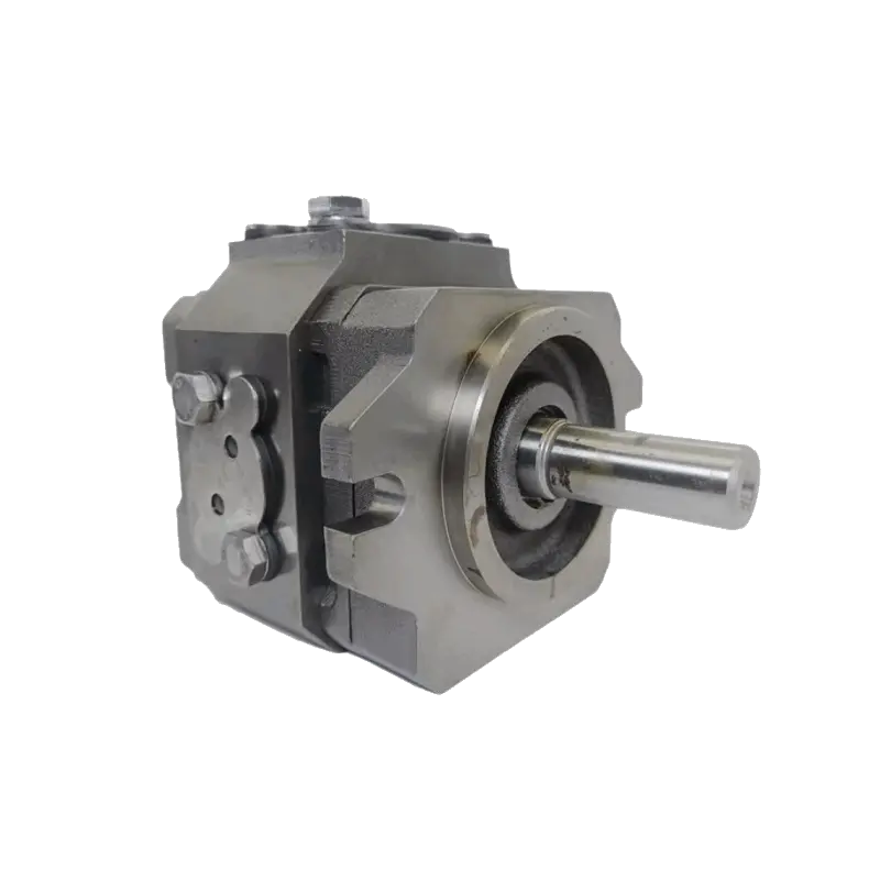
A gear pump normally contains two closely fitted gears inside a housing. As the gears separate near the inlet, fluid fills the spaces between the teeth and housing. Rotation carries the fluid around the outside of the gears. When the teeth mesh near the outlet, they displace the fluid into the pressure line.
Gear pumps are compact, relatively simple, and economical. They tolerate demanding environments better than many precision designs and are often used where dependable fixed flow is more important than highly adjustable output.
Their limitations can include pressure pulsation, relatively high noise, declining efficiency as clearances wear, and limited variable-displacement capability.
Vane Pumps
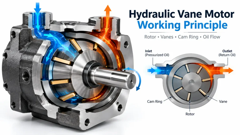
A vane pump uses a slotted rotor containing movable vanes. As the rotor turns inside an eccentric or adjustable ring, the vanes follow the surrounding surface. Chambers between adjacent vanes expand on the inlet side and decrease on the outlet side.
This design generally provides smoother flow and quieter operation than a basic gear pump. Some vane pumps can also change displacement by altering the position of the cam ring.
Close internal clearances make vane pumps sensitive to contamination, incorrect viscosity, and inadequate lubrication. Fluid cleanliness and proper inlet conditions are therefore especially important.
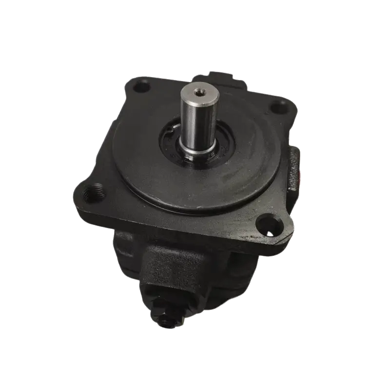
Piston Pumps
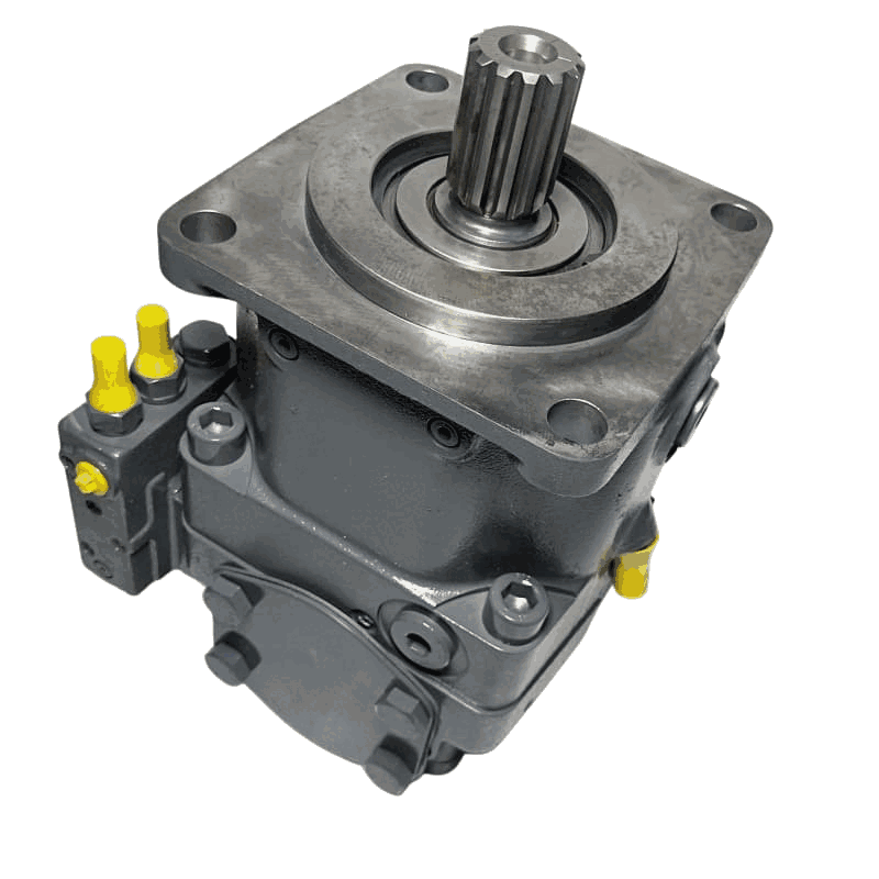
A piston pump uses multiple pistons moving within cylinders. During the inlet portion of the cycle, a piston retracts and the cylinder fills. During the discharge portion, the piston advances and forces fluid into the outlet.
Piston pumps can operate efficiently at high pressures and are commonly used when demanding duty cycles, precise control, or variable displacement is required. Axial arrangements position the pistons parallel or at an angle to the drive shaft, while radial arrangements place them around the shaft.
The tradeoffs are greater mechanical complexity, higher initial cost, tighter contamination limits, and more demanding repair procedures.
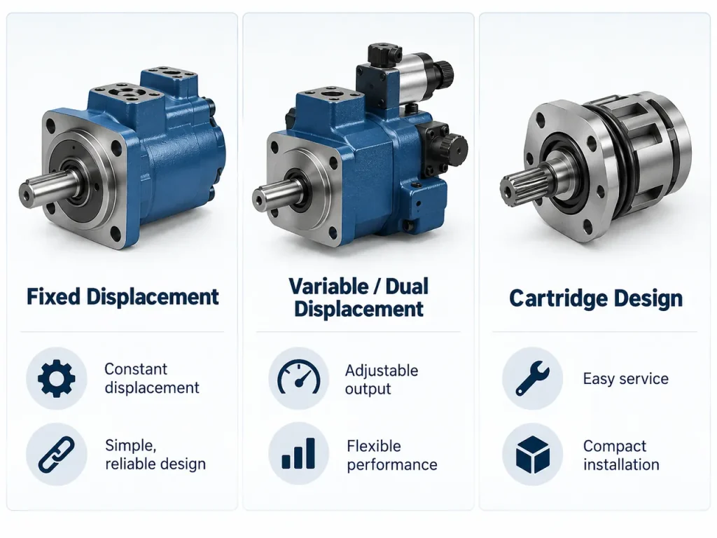
Fixed vs. Variable Displacement
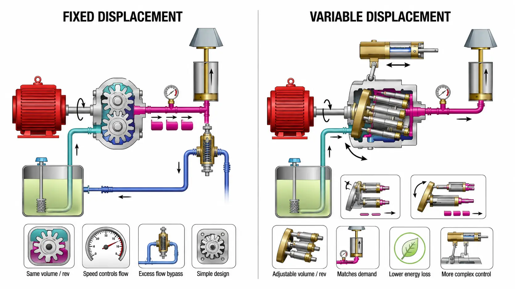
Fixed and variable displacement describe a different classification dimension. A fixed-displacement pump moves approximately the same theoretical volume during every shaft revolution. System flow changes mainly when pump speed changes or some flow is diverted.
A variable-displacement pump can change its output per revolution. This allows the pump to match demand more closely, reduce unnecessary flow, and limit energy losses. However, the control mechanism adds complexity and requires appropriate setup and maintenance.
| Factor | Gear pump | Vane pump | Piston pump |
| Internal mechanism | Meshing gears | Sliding vanes in a rotor | Reciprocating pistons |
| Typical flow quality | Moderate pulsation | Smooth | Smooth and highly controllable |
| Pressure capability | Low to medium | Medium | High |
| Efficiency potential | Moderate | Moderate to high | High |
| Noise | Often higher | Generally lower | Depends on design and operating condition |
| Contamination sensitivity | Moderate | High | High |
| Relative complexity | Low | Medium | High |
| Common fit | Simple fixed-flow systems | Quiet, stable industrial systems | High-pressure or variable-demand systems |
What Are the Advantages and Downsides of Hydraulic Pumps?
Hydraulic Pumps provide high power density, flexible power transmission, and precise control, but they can lose energy through leakage and throttling, generate heat and noise, and require disciplined fluid maintenance and high-pressure safety measures.
One major advantage is the ability to generate substantial force from compact equipment. Directional and proportional valves can control force, speed, acceleration, and direction without requiring a complex mechanical transmission between the power source and every actuator.
Hydraulic systems can also handle shock loads and hold or limit force through appropriate valve arrangements. Hoses and pipes make it possible to position actuators away from the pump, which is useful in mobile machinery and large industrial installations.
The disadvantages begin with energy loss. Internal leakage, mechanical friction, pressure drops, and valve throttling convert useful input power into heat. If the system cannot remove that heat, viscosity may fall, leakage may increase, seals may deteriorate, and pump life may shorten.
External leakage creates housekeeping, environmental, and safety concerns. Noise may result from pressure pulsation, vibration, cavitation, aeration, or structural resonance. Furthermore, changing a pump or raising system pressure without verifying the ratings of hoses, fittings, valves, and actuators can be dangerous. A documented hydraulic-system modification incident illustrates why every pressure-containing component must remain within its design limits.
How Long Do Hydraulic Pumps Last and Why Do They Fail?
There is no dependable universal average lifespan for a hydraulic pump. Service life can range widely because it depends on pump type, load cycle, pressure, speed, installation, inlet conditions, temperature, fluid cleanliness, oil quality, and maintenance practices.
Operating hours are more useful than calendar age, but even hours cannot be evaluated without context. A pump operating continuously near its limits in contaminated fluid will age differently from the same design running intermittently with clean fluid and stable temperature.
Condition trends provide a stronger basis for maintenance decisions. Useful indicators include delivered flow at a known pressure, case-drain flow, noise, vibration, oil temperature, pressure stability, particle counts, water content, and wear debris. Changes over time are generally more informative than a single measurement.
What Is the Most Common Cause of Hydraulic Pump Failure?
Fluid contamination is one of the most widely cited preventable causes of hydraulic pump failure. Hard particles can abrade surfaces, damage bearings, score valve plates, and enlarge precision clearances. The resulting internal leakage reduces volumetric efficiency and creates additional heat.
Contamination also includes water, air, incompatible fluid, and oxidation products. One published study of contamination-related hydraulic pump problems found that improved oil management substantially extended pump life in a specific industrial case. That result demonstrates the influence of fluid condition, but it should not be treated as a universal lifespan benchmark.
Other Common Failure Causes
- Cavitation caused by inadequate inlet pressure or excessive inlet restriction
- Aeration caused by air leaks, poor return-line design, or low reservoir level
- Excessive temperature and loss of suitable viscosity
- Incorrect or incompatible hydraulic fluid
- Operation above the pump’s pressure or speed rating
- Shaft misalignment or excessive radial and axial loading
- Dry startup, poor priming, or delayed lubrication
- Incorrect rotation direction
- Relief-valve faults or prolonged operation across a pressure restriction
Warning signs include unusual whining or knocking, unstable pressure, slower actuator movement, rising temperature, foaming fluid, increasing leakage, vibration, and declining flow. These symptoms should be investigated early because a deteriorating pump may release wear debris that damages downstream valves and actuators.
Service life can be extended by keeping the fluid within the required cleanliness and viscosity range, maintaining filters, preventing inlet restrictions, eliminating air leaks, controlling temperature, aligning the drive correctly, and monitoring performance trends. The root cause of a failed pump should also be corrected before a replacement is installed.
Frequently Asked Questions About Hydraulic Pumps
Can a Hydraulic Pump Run Without Fluid?
A hydraulic pump should not run dry unless its design and operating instructions explicitly permit it. Hydraulic fluid lubricates internal surfaces, supports sealing, and removes heat. Without fluid, sliding or rotating components can experience rapid friction, scoring, seizure, and seal damage.
After maintenance or fluid replacement, the inlet line and pump casing may need to be filled or primed. Air should be removed using a controlled startup procedure, and the pump should not immediately be loaded to full pressure.
Can Two Hydraulic Pumps Be Used in the Same Circuit?
Yes. Two pumps may be combined to provide staged flow, separate functions, redundancy, or efficient operation across different load conditions. For example, a circuit may use high combined flow for rapid actuator movement and unload one pump when the actuator reaches a higher-pressure working stage.
The arrangement requires properly selected check, unloading, relief, and directional valves. The pumps must also be compatible with the circuit’s flow, pressure, rotation, reservoir, filtration, and thermal capacity.
Should a Worn Hydraulic Pump Be Repaired or Replaced?
The decision should be based on inspection and performance testing rather than age alone. Repair may be appropriate when the housing, shaft, mounting surfaces, and major rotating components remain within recoverable limits and validated replacement parts are available.
Replacement may be more practical when damage is extensive, critical tolerances cannot be restored, repair cost approaches replacement cost, or downtime risk is high. In either case, the fluid, reservoir, filters, cooler, valves, and lines should be inspected for contamination or debris before the system returns to service.