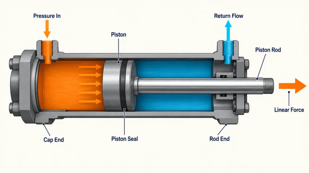
A Hydraulic Piston works by separating two fluid chambers inside a cylinder. When pressurized hydraulic fluid enters one chamber, it acts on the piston’s effective surface area and creates linear force. The piston then moves through the cylinder barrel, carrying the attached piston rod with it, while fluid from the opposite chamber returns to the reservoir.
Understanding this pressure-to-force conversion makes it easier to calculate load capacity, select seals and materials, diagnose performance problems, and determine whether a damaged piston can be repaired.
What Is a Hydraulic Piston?
A hydraulic piston is the movable, pressure-responsive component inside a hydraulic cylinder that converts fluid energy into linear mechanical force. It is not the complete actuator; it operates together with the barrel, piston rod, end closures, ports, bearings, and seals.
The piston fits closely within the honed bore of the cylinder barrel and divides that bore into two chambers. Seals installed around the piston restrict fluid from bypassing from the high-pressure chamber to the low-pressure chamber. The piston is mechanically connected to the piston rod, which transmits the generated force to a machine linkage, tool, platform, or other external load.
The Components Around the Piston
| Component | Primary Function | Important Design Consideration |
|---|---|---|
| Cylinder barrel | Contains pressure and guides the piston | Bore finish, straightness, strength, and wear resistance |
| Piston | Separates pressure chambers and generates motion | Effective area, seal grooves, material, and fit |
| Piston rod | Transfers force to the external load | Tensile strength, buckling resistance, surface finish, and corrosion |
| Head and end cap | Close the cylinder and support pressure loads | Port arrangement, structural strength, and sealing |
| Piston seals | Limit internal leakage between chambers | Pressure rating, friction, speed, and fluid compatibility |
| Rod seal and wiper | Limit external leakage and contamination entry | Rod finish, environment, temperature, and wear |
| Wear rings | Guide the piston and prevent metal contact | Side-load capacity, clearance, and material compatibility |
This distinction is important in technical discussions. The piston generates force inside the actuator, while the cylinder assembly contains the pressure and guides the movement. The hydraulic system also includes a pump, reservoir, valves, conductors, filtration, and control devices.
What Materials Are Hydraulic Pistons Made Of?
Hydraulic pistons are commonly made from steel, cast iron, or aluminum alloy. Steel provides high strength and wear resistance for demanding pressure and load conditions. Cast iron offers dimensional stability and favorable sliding characteristics in some industrial designs. Aluminum reduces moving mass but generally requires careful attention to pressure, wear, and surface protection.
The piston rod is usually made from high-strength carbon or alloy steel. Its working surface may be hardened, plated, or otherwise treated to resist scoring, corrosion, and seal wear. Material selection should reflect operating pressure, duty cycle, temperature, fluid chemistry, contamination exposure, and the consequences of component failure.
How Does a Hydraulic Piston Work Step by Step?
A hydraulic piston moves when a pump supplies fluid and a directional valve routes that fluid to one side of the piston. Pressure acting over the effective piston area produces force, while controlled flow determines how quickly the piston travels.
From Hydraulic Pressure to Linear Force
A pump moves hydraulic fluid through the circuit. Resistance from the external load causes pressure to build, and that pressure acts against the piston surface. According to the ideal cylinder relationships, piston force is related to pressure and effective area, while piston velocity is related to flow and area.
The basic theoretical relationship is:
Force = Pressure × Effective Area
Pressure is distributed through the confined liquid and acts perpendicular to the piston surface. A larger piston area therefore produces more theoretical force at the same pressure. Actual output is lower because the system must overcome seal friction, mechanical friction, return-line pressure, and other losses.
Extension and Retraction
A typical double-acting work cycle proceeds as follows:
- The pump draws fluid from the reservoir and sends it toward the control valve.
- The valve directs pressurized fluid to the cap-end chamber.
- Pressure acts on the full piston area, moving the piston and extending the rod.
- Fluid displaced from the rod-end chamber passes through the valve and returns to the reservoir.
- To reverse the movement, the valve sends pressurized fluid to the rod-end chamber.
- The piston retracts, and fluid from the cap-end chamber returns through the circuit.
Because the rod occupies part of the rod-side chamber, the effective area during retraction is smaller than the full piston area used during extension. At equal pressure, a conventional single-rod cylinder normally produces more extension force than retraction force. With equal inlet flow, it will usually retract faster because less fluid volume is needed to move the piston the same distance.
Single-Acting vs. Double-Acting Designs
A single-acting cylinder uses hydraulic pressure for movement in one direction. Gravity, a spring, or an external load returns the piston. This arrangement can be appropriate when powered movement is required in only one direction.
A double-acting cylinder can apply hydraulic power during both extension and retraction. It offers better bidirectional control and is common in equipment that must push, pull, position, or hold a load throughout a complete operating cycle.
How Much Weight Can a Hydraulic Piston Lift?
The weight a hydraulic piston can lift depends on system pressure, effective piston area, mechanical efficiency, mounting geometry, load direction, and the required safety margin. Theoretical force is a starting point, not a complete safe-load rating.
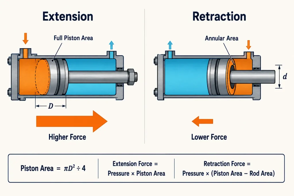
Calculating Extension and Retraction Force
For a circular piston, calculate the full piston area as:
Piston area = π × Bore diameter² ÷ 4
The theoretical extension force is:
Extension force = System pressure × Piston area
During retraction, subtract the piston rod area:
Retraction area = Piston area − Rod area
Retraction force = System pressure × Retraction area
Consider a cylinder with an 80 mm bore, a 45 mm rod, and an operating pressure of 160 bar. The following simplified example excludes friction and pressure losses.
| Calculation | Approximate Result |
| Full piston area | 5,027 mm² |
| Rod cross-sectional area | 1,590 mm² |
| Effective retraction area | 3,437 mm² |
| Theoretical extension force | 80.4 kN |
| Theoretical retraction force | 55.0 kN |
| Extension-force equivalent | About 8.2 metric tonnes-force |
| Retraction-force equivalent | About 5.6 metric tonnes-force |
These values describe theoretical cylinder force, not necessarily the amount of material that the complete machine can safely lift. Linkage geometry can multiply or reduce the force available at the actual load point.
Why Rated Force Is Not the Same as Safe Lift Capacity
A practical design must account for more than the nominal pressure and bore diameter. Relevant factors include:
- Seal and bearing friction
- Pressure loss through valves, hoses, and fittings
- Back pressure in the return line
- Off-center or side loading
- Dynamic impact and sudden load changes
- Piston rod buckling during long compression strokes
- Mounting-pin and frame strength
- Load angle and machine linkage geometry
- Pressure spikes and relief-valve settings
- Required design and safety factors
A larger bore increases force but also increases fluid volume, component size, and structural loading. A longer stroke increases reach but can raise buckling and alignment concerns. Safe capacity should therefore be verified at the system level using rated component data and the applicable engineering requirements.
How Are Hydraulic Pistons Sealed?
Hydraulic pistons are sealed by a coordinated set of dynamic and static sealing elements. Piston seals limit internal bypass between pressure chambers, while rod seals control external leakage and wipers help prevent dirt from entering the cylinder.
The Main Elements of a Cylinder Sealing System
| Sealing Element | Location | Main Function | Typical Failure Sign |
| Piston seal | Around the piston | Separates the two pressure chambers | Loss of force or uncontrolled internal bypass |
| Rod seal | In the cylinder head | Retains fluid around the moving rod | Visible oil on the rod |
| Wiper or scraper | Outer side of the head | Removes dirt, moisture, and debris | Contamination around the rod opening |
| Static seal | Between nonmoving components | Prevents leakage at joints and end closures | Oil around a fixed connection |
| Wear ring | Piston or head guide surface | Carries side load and prevents metal contact | Scoring, uneven seal wear, or excessive clearance |
A rod sealing arrangement generally relies on several interacting components rather than one seal working alone. Current cylinder sealing guidance identifies the rod seal, scraper or wiper, wear rings, and piston rod as principal elements of the system.
What Is the Most Common Hydraulic Seal?
There is no single seal that is best for every hydraulic position. Lip-type and U-shaped seals are widely used for dynamic piston and rod sealing because pressure energizes the sealing lip against the mating surface. O-rings are common in static joints and may also serve as energizers in compound seal arrangements.
Seal material must be compatible with the hydraulic fluid and operating temperature. It must also tolerate the expected pressure, sliding speed, surface condition, extrusion gap, and contamination level. A material that performs well in a moderate-temperature industrial circuit may deteriorate rapidly in a high-temperature, chemically aggressive, or abrasive environment.
Effective sealing requires a controlled balance. Excessive contact force raises friction and heat, while insufficient contact permits leakage. Correct groove geometry, bore finish, rod finish, concentricity, lubrication, and installation technique are therefore as important as the seal profile itself.
Can a Hydraulic Piston Be Repaired?
A hydraulic piston can often be repaired when the problem involves worn seals, replaceable wear components, light scoring, or restorable surfaces. Severe cracking, deformation, deep damage, or dimensions outside allowable tolerances may make replacement safer and more economical.
What Can Usually Be Rebuilt?
A cylinder rebuild commonly includes replacement of piston seals, rod seals, static seals, wipers, wear rings, and other serviceable components. The technician should also measure the piston, rod, barrel bore, bearing surfaces, grooves, and clearances rather than assuming that a new seal kit will correct the problem.
Light barrel damage may sometimes be corrected by controlled honing. A rod with limited surface damage may be refinished or restored if the completed surface remains within the required dimensional and finish specifications. The repair must also address the cause of failure, such as contaminated oil, excessive side loading, damaged mountings, incorrect seal material, or poor alignment.
When Replacement Is the Safer Option
Replacement should be considered when inspection finds:
- Cracks in the piston, rod, barrel, or end connection
- A bent rod that cannot be restored within tolerance
- Deep scoring, pitting, or corrosion across sealing surfaces
- Excessive material removal from previous repairs
- Distorted seal grooves or damaged threads
- Fatigue damage around welds or load-bearing connections
- An assembly that cannot pass dimensional or pressure testing
Repair economics also matter. A technically possible repair may provide poor value if machining, coating, testing, and downtime approach the cost of a suitable replacement.
Safe Repair Sequence
Stored hydraulic pressure and unsupported machine loads can cause serious injury. Applicable hydraulic safety requirements address hazards associated with hydraulic systems throughout installation, operation, adjustment, and maintenance.
A controlled repair process should include:
- Lowering or mechanically supporting all suspended loads.
- Isolating the machine from every relevant energy source.
- Releasing stored and residual hydraulic pressure.
- Cleaning the exterior before opening the cylinder.
- Disassembling the unit with suitable tools and containment.
- Measuring components and identifying the root cause of failure.
- Replacing or restoring parts according to verified specifications.
- Reassembling with clean fluid, components, and installation tools.
- Performing controlled leakage, function, and pressure tests.
- Documenting the repair and returning the system to service gradually.
High-pressure leakage should never be located with a hand or other body part. Repair and pressure testing should be performed by trained personnel using appropriate guarding, instruments, and procedures.
What Affects Hydraulic Piston Performance and Service Life?
Hydraulic piston performance is strongly influenced by fluid cleanliness, alignment, sealing-surface condition, temperature, pressure control, lubrication, and mounting geometry. Managing these factors reduces leakage, wear, unexpected movement, and premature failure.
Common Causes of Premature Failure
Solid contamination can scratch the barrel, damage seal edges, block small control passages, and accelerate abrasive wear. Misaligned mountings create side loads that concentrate force on bearings, wear rings, seals, and the piston rod. Excessive temperature can reduce fluid viscosity and shorten seal life, while repeated pressure spikes can overload seals and structural parts.
Rod corrosion or scoring is especially damaging because the affected surface passes through the rod seal during every cycle. Incorrect clearances can also allow seal extrusion or piston contact with the bore.
Practical Inspection and Maintenance Checklist
Routine inspections should cover:
- External leakage around the rod, ports, and end closures
- Changes in cycle time, force, temperature, or operating noise
- Scratches, corrosion, or uneven deposits on the exposed rod
- Loose pins, worn bushings, or misaligned mountings
- Hydraulic fluid condition and filtration performance
- Unexpected pressure fluctuations
- Uneven movement or hesitation during the stroke
Maintenance intervals should reflect actual operating hours, cycle frequency, contamination exposure, load severity, and environment. Trend-based observations are often more useful than waiting for a major leak or complete loss of motion.
FAQ
Why Does a Hydraulic Piston Drift While Holding a Load?
Drift can result from internal leakage across the piston seal, leakage through a control valve, or movement caused by temperature and load changes. Isolating the cylinder ports during a controlled diagnostic test can help distinguish cylinder bypass from valve leakage, but the procedure must be designed for the specific circuit and load.
Does Higher Flow Make a Hydraulic Piston Stronger?
Higher flow primarily increases piston speed, not static force. If excessive flow creates restrictions, heat, cavitation, or a large pressure drop, usable performance may actually decline. The pump, valve, conductors, return path, and cylinder must be sized as a coordinated system.
What Is Cylinder Cushioning and When Is It Needed?
Cylinder cushioning restricts fluid flow near the end of the stroke so the piston decelerates before reaching the end closure. It is useful when loads move quickly, carry significant inertia, or cycle frequently. Proper cushioning reduces impact, noise, mounting stress, and damage without causing excessive cycle time or back pressure.