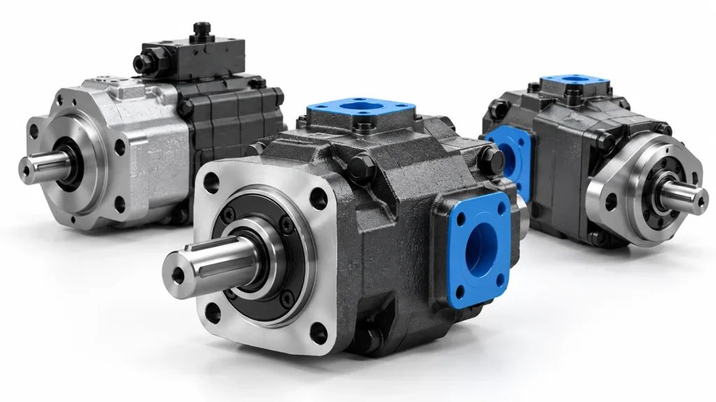
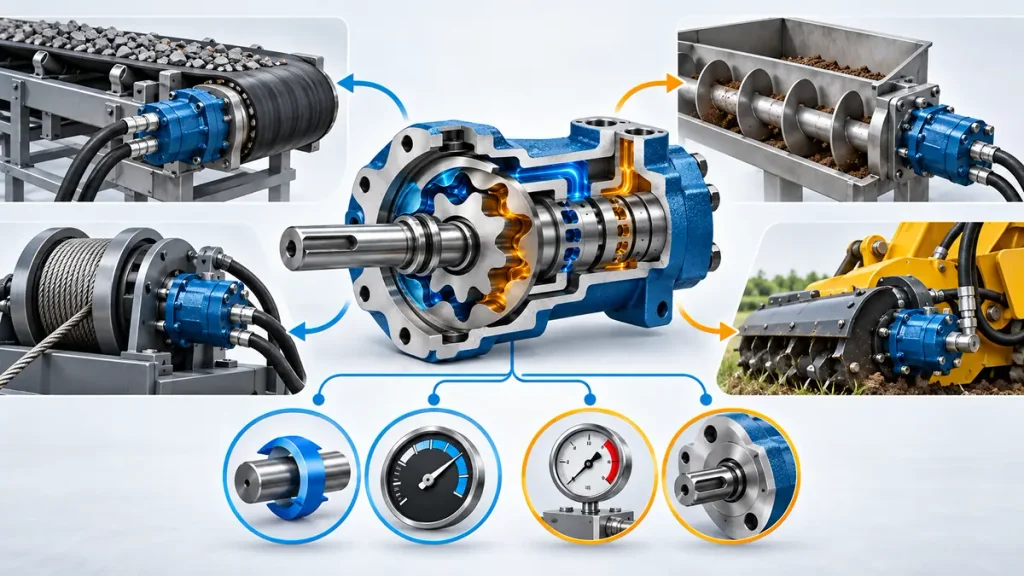
Mobile machines need torque at low shaft speed, and the usual answer is a fast motor with a gearbox. That costs axial length, adds a lubrication point and puts a reduction stage where space is tight. One compact housing does the same job for conveyor pulleys, winch drums, augers and sweeper brushes.
An orbital hydraulic motor is typically a fixed-displacement, low-speed, high-torque hydraulic motor that converts hydraulic pressure and flow into mechanical rotation through an internal gear mechanism and a synchronized distribution valve. In a common gerotor design, the inner rotor has one fewer tooth than the outer ring and moves eccentrically. A drive coupling transfers this motion to a concentric output shaft, allowing the motor to deliver substantial torque at relatively low speeds without necessarily requiring a separate reduction gearbox.
Port to shaft comes first, then the two valve designs, the limits under load, and the choice itself.
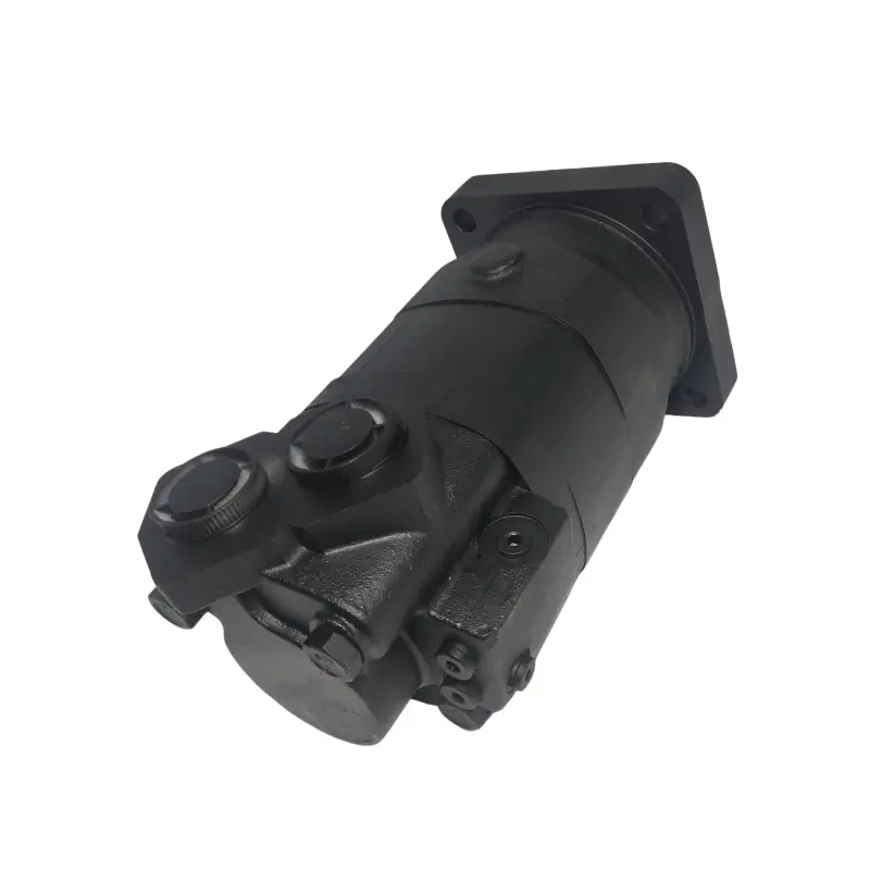
What Is an Orbital Hydraulic Motor?
It belongs to the low-speed, high-torque branch of internal gear motors, where the tooth set is the torque element, the valve is the timing element and the shaft is the output, with no reduction stage between them.
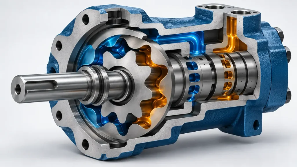
Three blocks do the work: the tooth set makes torque, the valve decides which chambers see pressure, and the shaft carries torque out. Because the reduction happens in the tooth set, no transmission, sump or alignment step is needed. Lists that divide motors into gear, vane and piston types add this one as a fourth group, but in design terms it is an internal gear motor, sharing that family’s sealing and leakage behaviour.
The Gerotor Set: How a One-Tooth Difference Creates Changing Chambers
Because the rotor has one tooth fewer than the ring and the two centres are separated by the eccentricity, every rotor tooth stays in contact with the ring. The contact points divide the gap into sealed chambers that grow on one side and shrink on the other, which is the volume change a positive-displacement motor needs. The arrangement is usually called a gerotor, described in Fundamentals of Hydraulic Motors, and a roller-type variant places rollers in the ring teeth to reduce friction.
The Valve and the Shaft: Timing and Delivery
The tooth set makes torque only if pressure reaches the right chamber at the right moment, which is the valve’s job: it turns in step with the rotor, feeding chambers that open and draining those that close. Because the two must stay synchronised they are mechanically linked, and the quality of that link sets low-speed smoothness, which is one of the real differences between orbit motor designs.
How an Orbital Hydraulic Motor Works
Oil enters a port, the valve admits it to the expanding chambers between rotor and ring, pressure on the tooth flanks produces a force offset from the rotor centre, the rotor turns and its axis orbits by the eccentricity, and a coupling carries that rotation to a concentric shaft while the valve drains the shrinking chambers.
The cycle repeats while flow arrives; what separates one motor from another is valve sealing, escaped flow and friction.
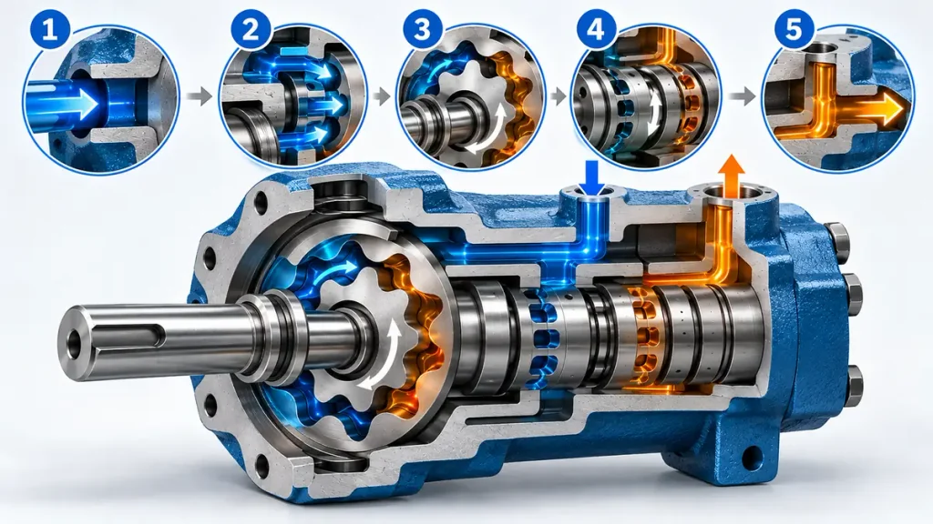
The Pressure Cycle, Port to Port
One tooth engagement repeats the same sequence:
- Inlet oil reaches the valve face at system pressure.
- The valve registers it against chambers whose volume is increasing.
- Pressure on the exposed flanks gives a resultant offset from the rotor centre, which makes it torque.
- The rotor turns, the contact line migrates, each chamber passes from expanding to shrinking.
- The valve connects shrinking chambers to the outlet, which returns oil at low pressure.
- The next engagement restarts the sequence, so torque stays continuous.
Several chambers pull at once, which is why the motor is smooth at low speed and why leakage, not tooth strength, sets the pressure ceiling.
From Orbital Motion to Concentric Rotation
The rotor centre rides a small circle offset from the ring centre, but torque has to leave through the ring centre, where the shaft sits. The bridge is a drive link, usually a cardan shaft with crowned splines in the rotor bore, which transmits torque and absorbs the offset. Hence the short housing: no crank throw, only the eccentricity. Because the coupling carries the orbital component, spline wear shows up as roughness and lost low-speed control long before the motor stops.
Why Pressure Sets Torque and Flow Sets Speed
Torque is pressure drop times displacement over two pi, or bar times cubic centimetres per revolution divided by 62.8 in practical units, before mechanical efficiency. Speed is flow over displacement.
The pressure that makes torque is inlet minus outlet, so back pressure subtracts torque. Leakage tracks pressure but hardly tracks speed, so at low speed the leaked fraction grows and both values fall short. The same relationships are derived from first principles in the guide to how a hydraulic motor works.
Spool Valve and Disc Valve: Where the Two Designs Differ
Both designs time the same tooth set, but they route leakage differently and load their sealing faces differently: a spool valve feeds pressure radially through slots in a rotating spool that is part of the shaft, while a disc valve feeds it axially through a lapped plate pressed against an end face and turned by a separate coupling.
In a spool-valve motor the shaft carries a machined commutator inside the rotor bore, and oil passes through longitudinal slots to reach the chambers radially, sealing on a close diametral fit. Clearance grows with wear and pressure, and spool diameter is limited by the rotor bore, capping displacement per frame size.
In a disc-valve motor the commutating plate sits at the end face behind a lapped port plate, turned by a coupling driven from the rotor; pressure on its back face nearly balances the front, so it stays in contact without heavy friction. Flat lapped faces can hold a smaller clearance than a cylindrical fit, which in practice favours volumetric efficiency at low speed, at the cost of sensitivity to flatness, oil film and contamination.
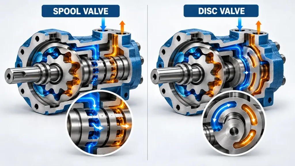
| Aspect | Spool valve | Disc valve |
| Pressure path | Radial, through slots in the shaft | Axial, through an end-face plate |
| Sealing | Close diametral clearance | Hydraulically balanced flat face |
| Leakage as wear develops | Rises with clearance | Rises if flatness or film is lost |
| Pressure capability | Usually limited by clearance and spool size in that frame | Often higher, but set by balance, flatness and filtration |
| Best fit | Compact, cost-sensitive, moderate pressure | Low-speed accuracy, higher pressure, long duty |
How an Orbital Motor Behaves Under Load
Running torque is not the number that starts a machine. Breakaway torque, minimum stable speed, case pressure and oil cleanliness decide whether a drive behaves in service, and each is a separate check rather than a margin hidden inside the displacement choice.
Starting Torque, Stall Torque and Minimum Stable Speed
Starting torque is lower than running torque, because a stationary motor must build an oil film and overcome static friction. A catalogue quotes running torque at a stated pressure drop and speed, and the torque available from rest is a separate entry rather than a fixed percentage of it. Orbital motors compare well because the tooth set presents a large pressure area at small displacement, but check the figure against the breakaway torque of the load and against whatever must move first: an unreleased brake, a counterbalance valve awaiting pilot pressure, or cold oil.
At stall the shaft does no work, so the power entering the motor is dissipated as heat, part of it through internal leakage and part through the relief valve or whatever else is bypassing flow. A stalled motor is therefore not a load-holding device; a brake valve or mechanical brake is.
Minimum stable speed is the slowest speed without stick-slip. Below it the friction characteristic interacts with oil compressibility and load stiffness, giving jerky rotation that no flow control can smooth. Flywheel mass, mounting rigidity, back pressure and viscosity shift it, so verify it with the actual load.
Case Drain, Back Pressure and Clean Oil
How leakage leaves the housing depends on the design. Some units have a dedicated case drain port, others return leakage internally to the low-pressure side. Where a drain port is fitted, its line has to follow the product documentation, because a restricted or shared drain raises case pressure and pushes on the shaft seal from inside, the usual cause of a seal that leaks with no shaft wear.
Back pressure is the second thief. Torque comes from the pressure difference, so every bar at the outlet removes torque, and filters, shared returns and long hoses all add to it.
Cleanliness is the third. The ISO 4406 code reports particles at or above 4, 6 and 14 micrometres per millilitre as three numbers, as the ISO 4406:2021 standard sets out. Orbital motors are forgiving compared with servo valves, but the valve face and tooth tips remain the tightest clearances, and contamination shows up as slow loss of low-speed smoothness and falling volumetric efficiency.
| Symptom in service | What it points to | First check |
| Speed below flow divided by displacement | Internal leakage past valve or tooth tips | Case drain flow, oil temperature |
| Will not start a load it can run | Breakaway torque or a brake not released | Relief setting, brake release pressure |
| Jerky rotation at low speed | Stick-slip, entrained air, low pressure | Bleed the circuit, confirm minimum speed |
Configurations Built Around the Same Tooth Set
The tooth set stays while the housing, bearings and valving change, which is how one mechanism covers duties from a conveyor pulley to a wheel hub; the configuration, more often than the displacement, decides whether the drive lasts.
| Configuration | What it adds | Typical duty |
| Standard | Two- or four-bolt flange, keyed or splined shaft | Conveyors, augers, mixers, rotary drives |
| Wheel | Hub flange and bearings that carry wheel loads | Vehicle and implement traction drives |
| Brake-integrated | Spring-applied, pressure-released brake in the housing | Winches and loads that must hold when flow stops |
| Dual displacement | Two displacements selectable by a shift valve | Travel drives needing torque and road speed |
The brake holds a stationary load and releases under pressure, but it does not control a descending load and does not replace a counterbalance valve on an overhauling winch.
Flanges, Shafts, Ports and Rotation
Four interface decisions are made last and cause most returns. The flange must match the mounting face and pilot diameter so the coupling runs true. The shaft must suit both coupling and radial load: keyed straight for a pulley near the flange, splined for a wheel hub, tapered for a press fit. The bearings set the permissible overhung load, so a pulley mounted far out reduces what the motor can carry without changing its torque rating.
Rotation follows the pressurised port and most units run either way, but the drain path and any integral check valve are not always symmetrical, so state the main direction and any reversing under load. A orbital cycloidal hydraulic motor datasheet shows how these details are quoted.
Where an Orbital Motor Is the Right Answer
It is right when the load already turns slowly, when the drive must survive dirt and shock, and when the package must be short and easy to seal; it is wrong when the duty is continuous high speed, or when efficiency at pressure dominates the operating cost over thousands of hours.
Duties That Suit Direct Low-Speed Drive
Output speed is low, often under a few hundred revolutions per minute, and starts, stops and reversals under load are frequent. The environment is dirty or vibrating, so a sealed drive is easier to protect than an exposed gearbox. Axial length is limited, flow control sets speed, and precise angular positioning is not needed. Under those conditions it is usually the cheapest way to get torque at the shaft, and it forgives brief stalls and shock loads. Agricultural implements are typical, and those drives are described under hydraulic parts for agriculture.
Where Another Motor Type Wins
For continuous running at several thousand revolutions per minute, an external gear motor or a high-speed piston motor with reduction is smaller and cheaper per unit of power. For high pressure with tight efficiency over long hours, an axial piston motor wins because it holds clearances better. Excavator travel and swing use piston motors with planetary reduction even at low output speed, since efficiency and pressure capability matter more there than compactness.
Specifying an Orbital Motor From the Duty
Start from the torque and speed the load needs, then work back through pressure, displacement and flow; a motor chosen from a displacement table alone ends up either oversized in flow or short of breakaway torque.
From the Duty to the Displacement
- Peak, continuous and breakaway torque at the shaft, including whatever a brake or counterbalance must release.
- Available pressure drop: pump setting minus line, valve and return losses.
- Displacement from torque and pressure drop, rounded up and corrected for mechanical efficiency.
- Flow for the target speed plus the volumetric loss expected there.
- Both ends of the speed range against maximum and minimum continuous speed.
- Case drain routing, seal limit and return back pressure.
- Overhung load, flange fit, port orientation and preferred rotation.
Before You Order
The last check covers items that never appear in a torque calculation but decide whether the drive lasts: displacement and tolerance, flange and pilot, shaft and overhung load, port size and orientation, rotation preference, drain arrangement, brake release pressure, viscosity range and cold-start temperature, filtration class, duty cycle including time at stall, and ambient conditions. Where a standard unit does not fit, the interface is what changes, which is the subject of custom hydraulic motor work.
Frequently Asked Questions
These three arrive once the mechanism is clear and the specification is being written; each changes a line on the order.
What is the difference between an orbital hydraulic motor and a gear motor?
A gear motor uses an external gear pair, runs faster, makes less torque per unit of size and usually costs less. An orbital motor uses an internal gerotor set, makes high torque at low speed without reduction and runs more smoothly there because several chambers pull at once.
Can an orbital hydraulic motor be used as a pump?
The gerotor element is reversible and gerotor pumps share the geometry, so a motor will move oil if driven. But drain routing, seal orientation, bearing lubrication and valve balance are arranged for motoring, so continuous pump duty should use a unit specified as a pump.
Are orbital hydraulic motors reversible?
Most are, because the tooth set and valve are symmetrical and direction follows the pressurised port. Confirm two things in writing: whether the drain path or an integral check valve favours one direction, and whether a fitted brake releases in both.