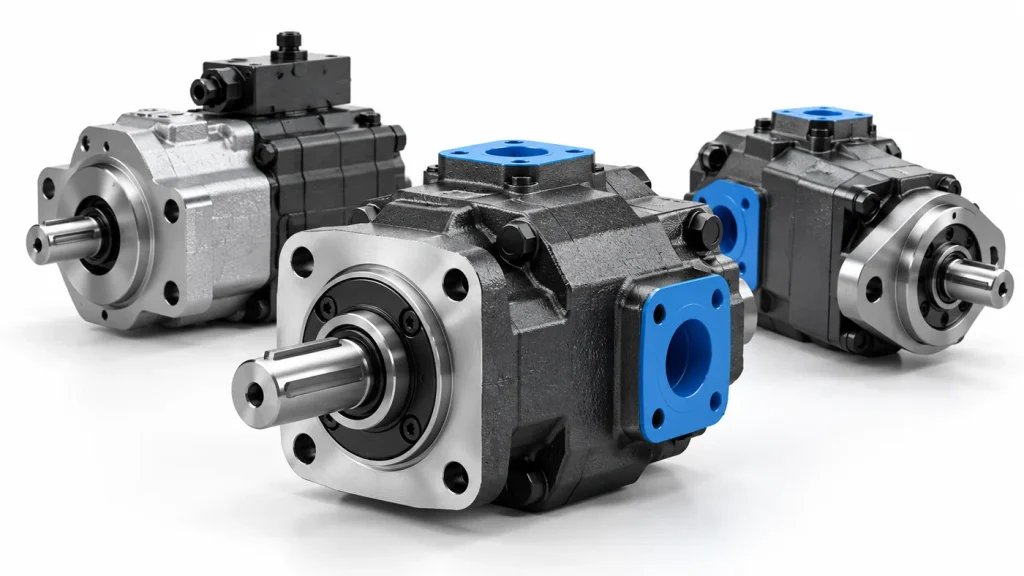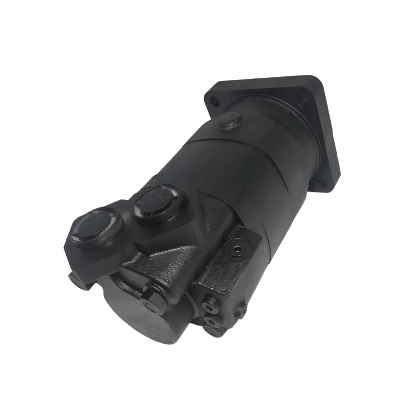
Most orbital motor enquiries start in the wrong place. A buyer sends a photograph of a failed unit, the catalogue answers with a displacement table, and the conversation jumps to part numbers before anyone records the torque and speed needed. That order explains why so many replacements stall, overheat or leak within a season.
Pick an orbital hydraulic motor by working backwards from the shaft: fix the torque and speed the load needs, convert them into a displacement and a pressure differential, then confirm that flow, duty limits, mounting and fluid conditions all match. Displacement alone confirms nothing.
The eight checks below follow that order.
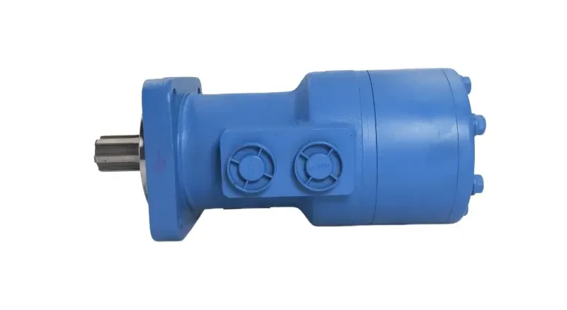
Start With the Load Profile, Not the Catalogue Page
Record the load, the duty cycle and the available supply before opening a catalogue. Starting under load, frequent reversing, long runs and a shared flow supply eliminate more candidates than any single torque figure.
Torque at the shaft is rarely one value. A conveyor needs a high breakaway torque to start a full belt, less once it moves, and a brief overload when a jam clears.
Data to Collect Before Comparing Models
| Parameter | Why it changes the selection | Where to get it |
| Breakaway and running torque | Starting torque is a separate rating, so a loaded start can rule out a size that suits running duty | Load calculation, builder data |
| Target speed range | Speed comes from flow, so the target fixes the flow required | Cycle timing, output speed |
| Flow and pressure at the motor | Shared circuits deliver less flow when another function works, and back pressure cuts the differential | Circuit diagram, gauges under load |
New Equipment Versus Replacement
New equipment leaves cycle timing, acceleration and space envelope to you, so torque and speed come from a load calculation. Replacement starts from evidence: model code, nameplate photograph, drawing, shaft and port arrangement, and an honest account of the failure.
What an Orbital Hydraulic Motor Does With Flow and Pressure
The differential across the gear set produces torque and the flow through it produces speed. More pressure adds torque without speed, more flow adds speed without torque, so a drive that stalls needs pressure or displacement rather than flow.
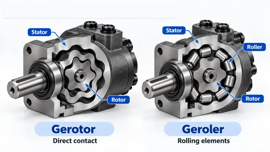
A rotor with one fewer tooth than its stator rolls inside a fixed ring, and the spaces between form sealed chambers that expand and contract. A distribution valve driven by the same shaft routes oil to the chambers in sequence, giving high torque at low speed. Every orbit motor manufacturer lists displacement, continuous pressure and speed limits per frame size, and those three values, not the series name, define the duty.
Gerotor vs. Geroler Designs: What Changes in Real-World Performance?
A gerotor set runs the rotor directly against the stator lobes. A geroler set places rollers in those lobes, so the rotor meets rolling elements instead of sliding surfaces, which reduces friction at the contact and is generally associated with smoother running at very low speed. It does not settle the selection, because efficiency and durability also depend on rotor clearance, roller retention and valve plate design. Treat it as one factor between models, not a verdict.
Why Orbital Motors Are Rated Low Speed, High Torque
Torque rises with displacement at a given differential, and displacement also sets how much oil each revolution consumes. A large displacement pulls hard at modest pressure but needs a lot of flow to turn quickly, and that appetite caps practical speed. Orbital motors suit direct drives that turn slowly and pull hard, while hydraulic motors of the high-speed piston type cover fast, low-torque duties and often need reduction gearing.
Size Displacement to the Torque and Speed You Actually Need
Size against two ceilings at once: the displacement that delivers the required torque at the differential the system can hold, and the displacement that reaches the target speed at the flow that reaches the motor. A candidate must satisfy both.
Keep differential in bar, displacement in cubic centimetres per revolution and flow in litres per minute, and the results come out in newton metres, revolutions per minute and kilowatts.
| Quantity | Formula | Units |
| Theoretical torque | T theory = differential × displacement / 62.8 | N·m, bar, cm³/rev |
| Delivered torque | T output = differential × displacement × mechanical efficiency / 62.8 | N·m |
| Theoretical speed | n theory = 1000 × flow / displacement | rpm, L/min, cm³/rev |
| Delivered speed | n actual = 1000 × flow × volumetric efficiency / displacement | rpm |
| Hydraulic input power | P hydraulic = differential × flow / 600 | kW, bar, L/min |
Every formula uses the differential between inlet and outlet, not the gauge reading at the inlet. A motor fed at 190 bar with 15 bar in its return works at 175 bar, and that missing 15 bar is torque never delivered.
A conveyor drive needs 450 N·m at 150 rpm, with 175 bar available, 30 L/min reaching the motor, a mechanical efficiency of 0.90 and a volumetric efficiency of 0.94.
| Displacement | Theoretical torque | Delivered torque | Theoretical speed | Delivered speed | Result |
| 160 cm³/rev | 446 N·m | 401 N·m | 188 rpm | 176 rpm | Torque short |
| 180 cm³/rev | 502 N·m | 451 N·m | 167 rpm | 157 rpm | Meets both, thin margin |
| 200 cm³/rev | 557 N·m | 502 N·m | 150 rpm | 141 rpm | Speed short at 30 L/min |
| 250 cm³/rev | 697 N·m | 627 N·m | 120 rpm | 113 rpm | Speed well short |
Only the 180 cm³/rev unit satisfies both constraints, and it does so with almost no torque margin. The 200 cm³/rev unit would need about 32 L/min to reach 150 rpm, which is a circuit change rather than a motor change. That band spans several frame sizes, and an orbital cycloidal hydraulic motor built for agricultural and mobile duty sits inside it.
Theoretical Versus Delivered Torque
Volumetric efficiency accounts for oil slipping past the gear set and valve plate without doing work, and appears as lost speed. Mechanical efficiency accounts for friction in the gear set, valve drive and bearings, and appears as lost torque. Both fall as pressure rises and as clearances wear, which is why a fixed percentage derating is unsafe.
The Hydraulic Rules That Underpin Motor Sizing
Training material condenses hydraulics into a short set of rules, commonly seven, and three govern motor sizing. Flow sets speed and pressure sets force, so a stalled actuator is a pressure problem and a slow one is a flow problem. Pressure responds to load resistance rather than being created by the pump. Power is pressure times flow divided by 600, the check that closes the loop: 8.75 kW goes in and about 7.4 kW reaches the shaft. Pascal’s law, that pressure in a confined fluid is transmitted undiminished, explains why the same pressure on a larger displacement yields more torque.
Set Pressure Limits by Duty Cycle, Not by the Nameplate Maximum
A pressure rating is a set of conditions, not a number. Continuous, intermittent and peak differentials are separate permissions, each with its own duration and frequency defined for that exact model. A peak value used for continuous duty puts the motor outside its envelope from the first shift.
The continuous figure is the one to design around, because it is permitted indefinitely. The intermittent figure applies for a stated period at a stated frequency, long enough to climb a ramp or clear a jam, and rests on thermal behaviour rather than instantaneous strength. The peak figure covers momentary events and protects the motor from spikes. Take all three from the model documentation, because the durations vary with gear set size and valve design.
- Pressure spikes. Valve closure and load reversals send excursions above the gauge reading, absorbed by bearings and seals.
- Return back pressure. A shared return or restricted filter cuts the differential and raises case pressure at once.
- Rated flow and speed. Permitted flow at operating viscosity sets a speed ceiling unrelated to pressure.
- Input power. Running near a pressure limit converts more input into heat, which feeds back into viscosity.
Why Maximum Pressure and Maximum Speed Are Not a Package Deal
The two maxima come from different limits: pressure from structure and sealing, speed from lubrication, bearing and filling. Nothing in the table says both can be reached together, and on many models they cannot. The permitted region is an envelope or a set of curves, and any point outside it needs written confirmation.
Know Where an Orbital Motor Fits and Where It Does Not
Orbital motors suit compact direct drives needing high torque at low to moderate speed, and tolerate uneven loads at moderate cost. They are a poor fit for sustained high speed, precise motion control and duties where part-load efficiency dominates.
The comparison is deliberately qualitative, because every category overlaps the next. Where a duty needs higher speed and pressure, a piston motor manufacturer will publish higher ceilings at higher cost.
| Consideration | How to read it |
| Torque at low speed | Orbital and radial piston types are usually first choices; axial piston types generally need reduction gearing |
| Speed range | Orbital motors are typically positioned for low to moderate speed; high-speed duties usually point elsewhere |
| Pressure and efficiency | Efficiency varies more between models than between categories, so compare curves at your operating point |
| Contamination and cost | All types need filtration, with levels set by the specification; orbital drives are usually the cheaper compact option |
Applications That Reward Orbital Drives
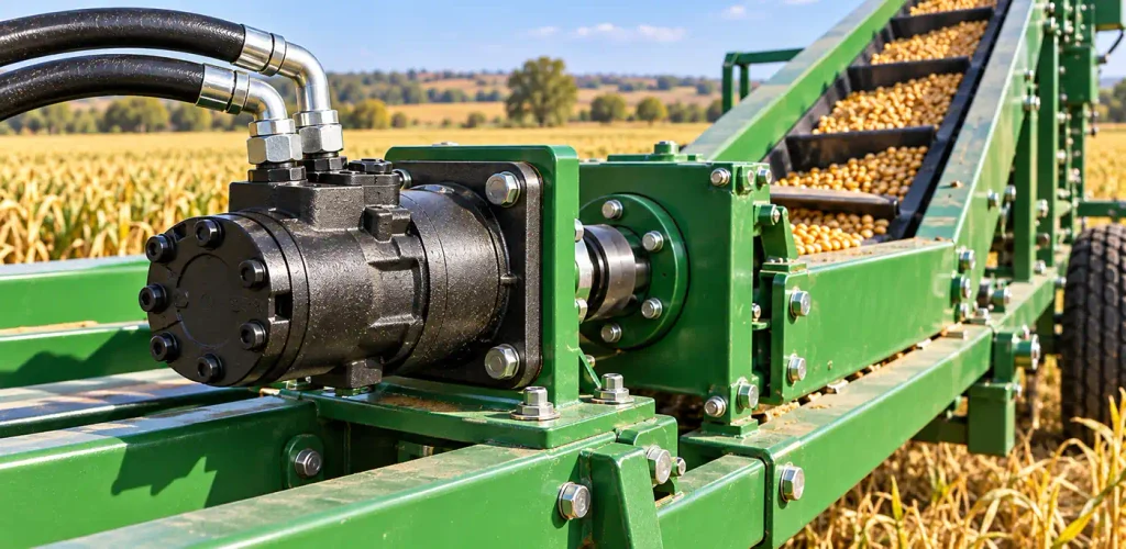
- Agricultural machinery and implement drives, including tractor and harvester auxiliaries
- Conveyors and material-handling equipment, where breakaway torque under a full belt sets the size
- Winches and compact drives, where the motor sits close to the load
- Sweepers and similar low-speed, high-torque equipment with frequent starts and reversals
Continuous high-speed duties such as cooling fan drives sit outside the typical envelope. They are worth considering only after continuous speed, load and thermal limits are confirmed for the model.
Verify the Shaft, Flange, Ports and Drain Before You Order
A motor that meets the torque and speed requirement but does not fit the machine is still the wrong motor. Confirm shaft, flange, ports, rotation and drain against the drawing, not against the series name.
Purchase orders go wrong here, because a matching series name says nothing about shaft length, ports or configuration.
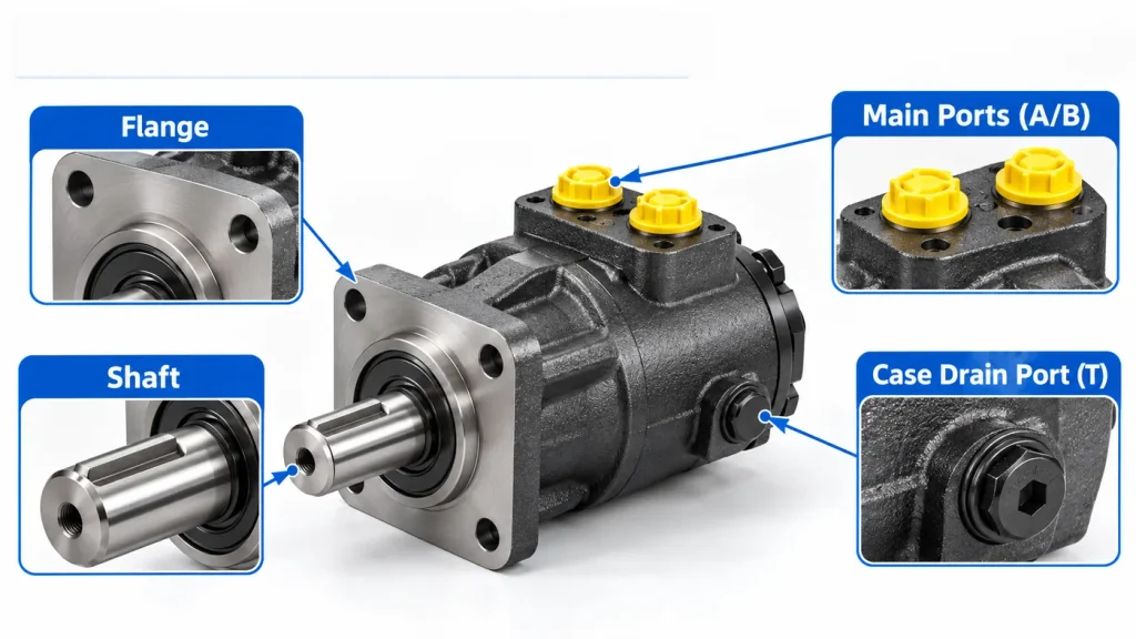
| Interface item | What to confirm | If it is wrong |
| Shaft | Spline or keyed, diameter, length, keyway, tapped end | Coupling will not fit, or bottoms in the bore |
| Flange | Pilot diameter, bolt circle, bolt size, register depth | Will not seat, or seats off-centre |
| Ports | Thread standard, size, angle and side | Hoses will not route, or foul the frame |
| Rotation | Required direction and how it is specified | Runs backwards, and the valve plate cannot be reversed |
| Drain | Whether a drain port is required and where it sits | Seal and bearing housing pressurised, leading to leaks |
| Envelope | Overall length, body diameter, fitting clearance | Fouls structure, or cannot be serviced |
Shaft, flange and port options change from one frame size to the next, so a hydraulic orbit motor sold in several sizes can look identical in a photograph while differing in all three.
Shaft Loads, Return Back Pressure and Case Drain
Three checks are omitted most often, and each fails quietly.
Radial and axial shaft loads. A motor driving through a sprocket, pinion or belt carries a side load the shaft and bearings must absorb, permitted at a defined distance from the shoulder. A heavy sprocket hung far out, or a belt tensioned to its limit, can exceed it even when the torque is correct.
Return-line back pressure. Restrictions downstream add to outlet pressure, and because torque comes from the differential, back pressure removes torque while loading the shaft seal. Measure it under load.
Case drain. Many orbital motors need an unrestricted drain back to tank, at the highest point the port allows and never teed into a loaded return line. Confirm whether a drain port is fitted and what case pressure the seals permit.
Match the Fluid, Temperature and Cleanliness to the Motor
Viscosity, oil temperature and contamination decide whether the motor reaches its rated volumetric efficiency and life. Confirm the viscosity window, cleanliness level and seal material for the exact model from the manufacturer’s specification.
Viscosity that runs too high, typically on a cold start, starves the inlet and can damage the gear set before the oil warms. Viscosity that runs too low, usually from overheating or the wrong grade, slips past clearances and shows up as lost speed. The fluid grade has to hold that window across the full ambient range, and the mineral oil categories in ISO 11158 are written as minimum requirements broad enough for different climates. Filtration rating and cleanliness code come from the specification for that size.
Seal and Fluid Compatibility
Seal material decides which fluids the motor handles and at what temperature. Mineral oil, biodegradable ester fluids and fire-resistant fluids place different demands on nitrile and fluorocarbon elastomers, and a seal suited to one may swell with another. Low-temperature starts add a condition the seal must survive.
Reduce the Shortlist to One Motor
Work through the checks in a fixed order and reject rather than rank. Each failing step removes a candidate outright, and what survives the last interface check is the motor to quote.
- Fix the output torque at the shaft, including breakaway and peak conditions.
- Fix the target speed and the flow reaching the motor at each point.
- Establish the differential actually available, after return back pressure.
- Calculate the displacement needed for torque and the one allowed by speed.
- Reject sizes that fail either constraint, then check power and temperature rise.
- Compare survivors on efficiency at the operating point, not at peak.
- Confirm continuous, intermittent and peak ratings with their conditions.
- Verify shaft, flange, ports, rotation and drain against the drawing.
FAQ
The three questions below cover what the arithmetic leaves out: the prime mover behind the pump, reversing a motor into pump duty, and why a motor that met its speed requirement still loses speed.
Does the electric motor driving the pump change which orbital motor I need?
Only indirectly. The prime mover sets the power available to the pump, and the pump sets the flow and pressure that reach the motor, so an undersized electric motor shows up as a hydraulic motor that cannot hold speed. Check that its rated output covers the pump input at your duty point.
Can an orbital hydraulic motor be used as a pump?
Not automatically. Most orbital motors are built for one direction of energy flow, and reversing the role changes the lubrication path, shaft seal load and the behaviour of the distribution valve. Some models are permitted in pump duty, some are not, and efficiency and speed range differ from the motor rating.
What causes an orbital motor to lose speed under load?
Loss of speed is usually a flow problem rather than a torque problem. Check whether flow reaching the motor drops when other functions operate, whether the differential falls below what the load requires, and whether internal leakage has grown through wear. Oil temperature belongs on the same list, because thin hot oil slips past the gear set.