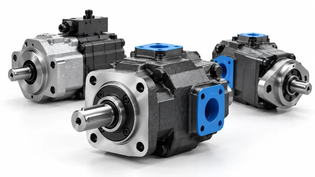
Hydraulic gear motors sit at the end of a power train that begins at a diesel engine and finishes at a rotating shaft, yet they are the least discussed part of that chain. Buyers compare displacement figures and swap a unit when a conveyor slows, but few look inside the housing, which is why most complaints trace back to specification.
A hydraulic gear motor is a fixed-displacement rotary actuator that converts hydraulic pressure and flow into shaft torque and rotation. Pressurised oil pushes against the exposed tooth flanks of two meshing gears; because each gear is held on its own centre by bearings, that force acts at a radius and the output shaft turns. Pressure difference sets torque, oil volume sets speed, and the gear geometry fixes the ratio between them.
The sections below follow the oil through one revolution, put numbers on what the shaft delivers, and show how to read the symptoms when output fades.
What Is a Hydraulic Gear Motor?
It is a positive-displacement motor whose swept volume is fixed at the factory. Every revolution passes a volume of oil equal to the displacement, and nothing inside can change that volume while it runs. That one decision explains most of its behaviour, from a near-constant torque per bar to an output no control signal can trim.
In a circuit the pump turns mechanical power into hydraulic power and the motor reverses the conversion. The gear type is the simplest rotary actuator available: two gears, a housing, wear plates, and a shaft. Fewer parts means fewer failure modes and easier replacement, at the price of a fixed displacement and modest tolerance for pressure at the gear tips.
Displacement is set by tooth geometry and face width, so a wider gear set raises torque for a given pressure and lowers the speed available from the same flow. Pressure difference produces torque and flow produces speed, which is why a stalled motor can hold full pressure at zero speed, limited only by the relief valve. The general conversion is covered in the guide on how hydraulic motors work.
The Components That Do the Work
| Component | Function | What failure looks like |
| Housing and covers | Locate gears, contain pressure, form the chambers | Scored bore, polished wear tracks |
| Drive and idler gears | Carry torque, double displaced volume per turn | Tooth pitting, flank wear |
| Wear plates | Control axial clearance, the main leakage path | Leakage rising, speed lost under load |
| Bearings and seals | Absorb radial load, retain oil, route leakage | Seal seepage, whine, rising drain flow |
The bearings run on a controlled bleed of oil from the high side, vented to the low side or a drain port. That bleed keeps them alive and is also a leak doing no useful work, so wear makes a motor run hotter and slower.
How Does a Hydraulic Gear Motor Work?
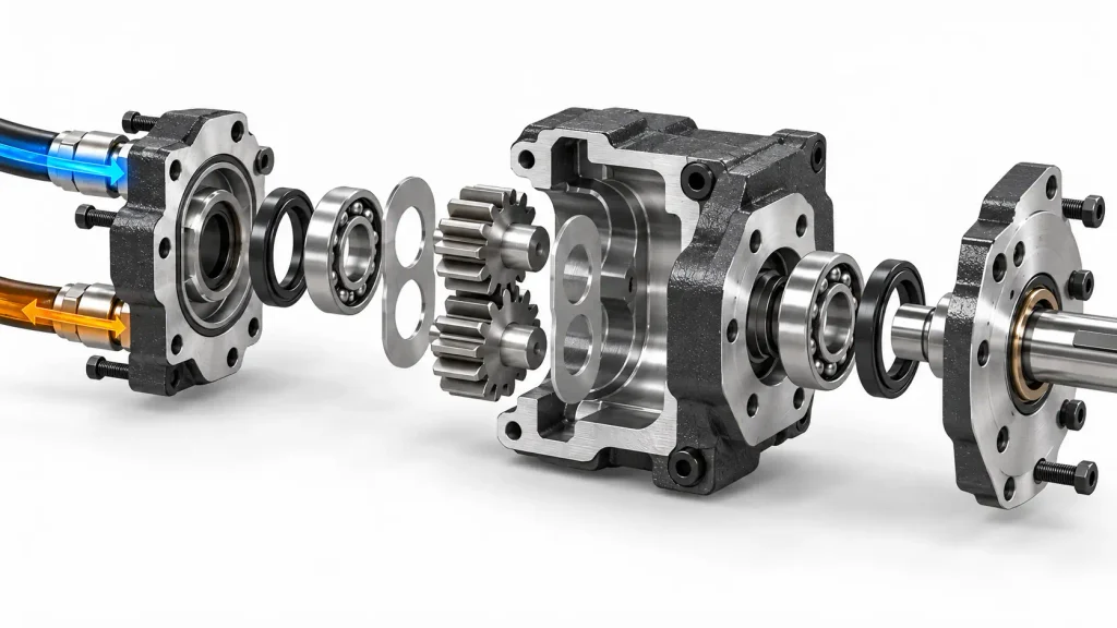
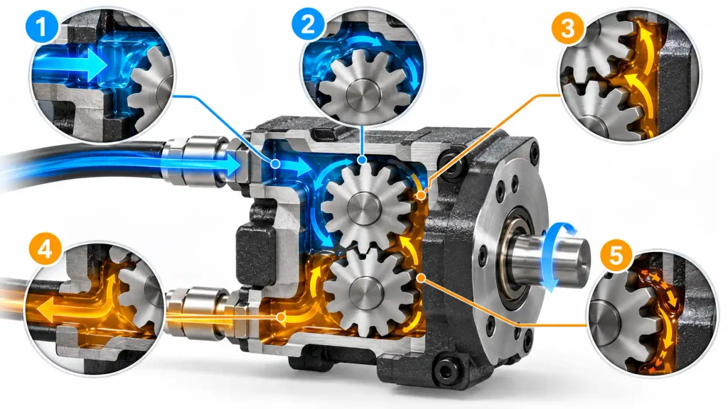
Oil enters the port that opens onto the side where teeth are separating, so the spaces between them are expanding and fill completely. Because the outlet sits at lower pressure, every flank exposed to inlet pressure carries a net force at a radius from the gear centre. The drive gear turns, carries the idler through the mesh, and each tooth space transports a fixed volume around the housing wall to the outlet, where re-meshing pushes it into the return line.
The mesh is the seal: where the gears touch, high and low sides are separated along the line of action, with tip and face clearances closing the boundary. No valves sit in the working path, which is why the general account of hydraulic motors applies here with so few parts to go wrong.
Following the Oil Through One Revolution
- Admission. Oil fills the spaces where the gears unmesh as the volume there grows.
- Loading. Pressure on the exposed flanks produces rotation, since each gear is held on its own centre.
- Transport. The drive gear carries the idler, and each tooth space moves its trapped volume around the housing. Spaces per revolution times volume per space is the quoted displacement.
- Discharge. On the outlet side the space collapses and oil leaves against back pressure.
- Leakage. A fraction slips past faces and tips, and some passes through the bearings.
Displacement, Torque, and Speed
Displacement in cubic centimetres per revolution is fixed by the gear set, pressure drop in bar by the load and relief valve, and flow in litres per minute by the pump.
Theoretical torque in N·m = (pressure drop in bar × displacement in cm³/rev) / 62.83
Actual shaft torque in N·m = (pressure drop in bar × displacement in cm³/rev × mechanical efficiency) / 62.83
Shaft speed in rpm = (1000 × flow in L/min × volumetric efficiency) / displacement in cm³/rev
The constant 62.83 folds the unit conversions together, including the 2π that turns a force at a radius into torque. The two torque lines differ by the losses in bearings, mesh, and seal.
| Displacement (cm³/rev) | Pressure drop (bar) | Mechanical efficiency | Theoretical torque (N·m) | Actual torque (N·m) | Flow for 1,500 rpm at 92% volumetric efficiency (L/min) |
| 10 | 150 | 0.90 | 23.9 | 21.5 | 16.3 |
| 20 | 200 | 0.88 | 63.7 | 56.0 | 32.6 |
| 32 | 180 | 0.85 | 91.7 | 77.9 | 52.2 |
The gap between the torque columns runs at ten to fifteen percent and widens with load. Sizing from theoretical torque buys a unit that stalls on the first cold morning; the working figure is the continuous rating.
Speed layers the same way: the volumetric term covers oil that slips through clearances. A new unit may show 0.93 to 0.95, and after thousands of hours on dirty oil that can fall into the low eighties, so a motor that held 1,500 rpm when new holds closer to 1,300 rpm.
How Hot Oil and Internal Leakage Affect Performance
As oil warms, thinner oil slips more easily through the axial clearance at the gear faces and the radial clearance at the tips. Volumetric efficiency drops, so at a fixed inlet flow the shaft turns more slowly and a motor that held speed when cold sags under load.
Theoretical torque does not change, because it depends on pressure drop and displacement only. If the system holds the same pressure difference, shaft torque is unaffected by temperature; the loss appears in the flow budget, since leaked oil is oil the pump paid for and the motor never converted.
What Are the Different Types of Hydraulic Gear Motors?
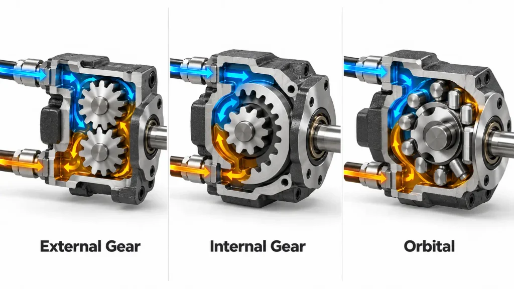
Three families are normally distinguished: external gear motors, internal gear motors, and orbital motors, the last built on a gerotor. They differ in how the sealed volume forms, not in the principle of energy conversion. Some catalogues call orbital motors epicyclic, which confuses buyers, since a planetary set is a reduction stage.
External Gear Motors
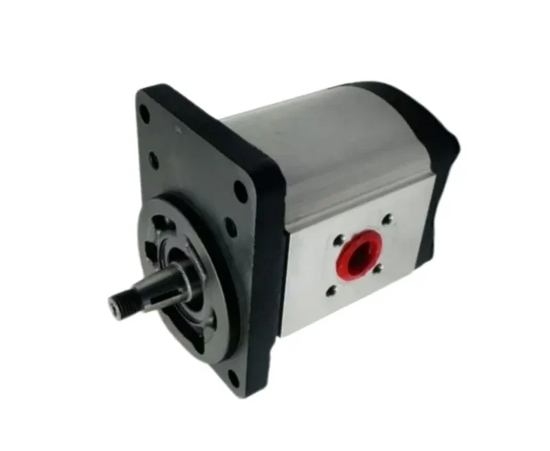
Two gears mesh externally, with the drive gear on the output shaft and the idler on a bearing pin. Common mobile sizes run from a few cubic centimetres per revolution to around fifty. The unit is short axially, cheap to produce, and easy to rebuild, and it turns fast, which suits fan drives, conveyor pulleys, and pump drives. The limit is the separating force, so a frame’s continuous rating is set by its bearings. A representative external gear motor shows how that trade shapes a mobile frame.
Internal Gear Motors
An externally toothed pinion runs inside a larger internally toothed ring, usually with one more tooth, the two turning about offset centres so the crescent gap between them forms the sealed volume. Because teeth engage progressively instead of along one line of contact, flow is smoother and the unit quieter. It is not automatically a low-pressure or silent device; both depend on the frame and the operating point.
How Are Orbital Motors Different?
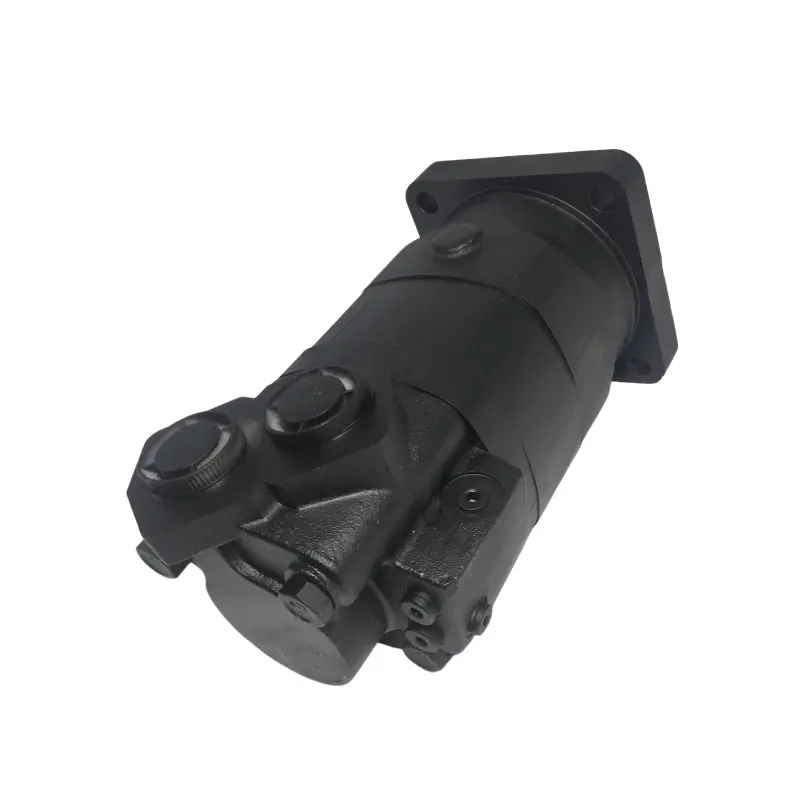
An orbital motor uses an inner rotor with one fewer tooth than the outer ring, both turning about offset centres inside a fixed stator. Cells between the rotors expand on the inlet side and contract on the outlet side, driving the shaft through a coupling that converts orbital motion into rotation. A compact unit displaces several hundred cubic centimetres per revolution, giving high torque at low speed without a gearbox, and runs smoothly at a few revolutions per minute where a gear motor would show stick-slip. Gear motors are speed devices that tolerate load; a hydraulic orbit motor is a torque device that tolerates slow rotation.
| Family | How the sealed volume forms | Speed character | Torque per unit size | Best-fit duty |
| External gear | Between teeth of two meshing gears, sealed by wear plates | High, often 500 to 3,000 rpm | Moderate | Continuous rotary drives, fans, conveyors |
| Internal gear | Crescent gap between pinion and ring | Medium, smoother and quieter | Moderate | Low-noise medium-pressure drives |
| Orbital | Cells between inner and outer rotors | Low to medium, down to a few rpm | High | Wheel, winch, and auger drives |
Hydraulic Gear Motor vs. Gear Pump: What’s the Difference?
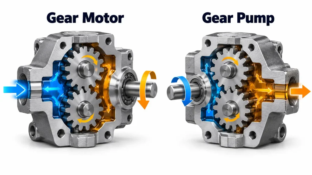
Both are positive-displacement gear machines with the same geometry; the difference is the direction of energy flow and the design changes made to survive it. A pump is built to be driven: its shaft accepts input torque, its inlet suits suction, and its leakage returns internally without pressurising the housing. A motor is built to drive: its shaft delivers torque, its bearings survive the separating forces, and its leakage must exit without pushing past the seal.
| Feature | Pump design intent | Motor design intent |
| Shaft | Accepts torque through a coupling | Delivers torque, often with belt side load |
| Bearings | Sized for gear plus drive side load | Sized for output torque and reversing |
| Ports | Inlet larger than outlet to avoid cavitation | Often symmetrical for either direction |
| Drain | Leakage returns to the inlet, housing near suction | Separate port, leakage leaves at low pressure |
| Rotation | Usually a single direction | Fixed or bi-directional, per the designation |
The drain row is where conversions go wrong. A pump returns leakage to the inlet, keeping the housing near suction pressure. A motor must remove it from a housing that would otherwise climb towards inlet pressure, which is why many models carry an external drain run to tank unrestricted. Reversibility is a property of the gear pump geometry.
Can a Gear Pump Be Used as a Gear Motor?
In principle yes: the geometry is reversible, and a gear pump fed with pressurised oil will rotate and produce torque, which is a fair way to prove a circuit on a bench.
As a permanent drive it is a compromise. The housing of an internally drained pump pressurises once it becomes a motor, loading the shaft seal and distorting clearances. Bearings sized for input torque do not expect continuous output torque and belt side load, inlet and outlet are often different sizes, and some pumps carry a check valve or unidirectional drain that will not pass oil a motor needs. It therefore suits short-duty, low-pressure, single-direction work with an unrestricted return. The full conditions appear in the guide on running a hydraulic pump as a motor.
How to Tell If a Hydraulic Gear Motor Is Going Bad
Gear motors usually degrade gradually. The gears wear the plates and the bore, axial clearance opens, more oil slips to the low side, and the motor loses speed under load long before anything breaks. Sudden failure still happens, usually from a foreign object through the mesh or a starvation event that destroys the film, so a motor that stops dead often reports a circuit problem.
| Symptom | Probable cause | How to confirm |
| Speed falls under load, no-load speed normal | Leakage past worn plates or tips | Case drain flow against the data sheet |
| Weak starting torque, will not break a load away | Wear, or relief set too low | Gauge at the inlet during a start |
| Housing hot, outlet oil hotter than inlet | Leakage converting pressure into heat | Temperature rise across the motor |
| Oil at the shaft seal | Seal failure, or a blocked drain | Inspect drain line and filter |
| Metallic whine or rattle under load | Bearing wear, or cavitation | Inlet vacuum gauge, oil sample |
| Case drain flow rising over months | Progressive wear, the most reliable indicator | Trend at a fixed temperature |
What Shortens Gear Motor Life
Six conditions account for most premature failures, and only one starts inside the motor. Contamination embeds particles in the plates and scores the faces, opening the clearance efficiency depends on; a gear motor tolerates more than a piston motor, but tolerance is not immunity. Aeration from a restricted inlet destroys the film, misalignment and belt side load overwork the bearings, excess backpressure distorts clearances, and wrong viscosity starves the inlet or leaks past it.
These mechanisms are shared with the gear pump, so pump-life guidance applies, yet no hour figure attaches to either. Life depends on the pressure spectrum, hours at pressure, cleanliness, temperature, and shaft loading. Measure rather than predict: log case drain flow and no-load speed quarterly, and treat a drift of ten to fifteen percent as the trigger to plan replacement.
Common Hydraulic Gear Motor Applications
Gear motors suit drives that turn at moderate to high speed, stay inside the published continuous rating, and work where a more delicate unit would not survive. They are the default for auxiliary rotating functions, not for the main traction circuit.
| Industry | Typical driven point | Why a gear motor fits |
| Agriculture | Header reel, grain auger, fan drive | Dust in the oil, wide ambient range, field replacement |
| Construction | Roller drum, attachment rotation, paver conveyor | Compact, tolerant of site dirt, easy to service |
| Material handling | Forklift fan drive, warehouse conveyor | Fast start and stop, small envelope |
| Municipal vehicles | Sweeper brush, salt spreader, platform rotation | Speed set by flow, no electrical hazard when wet |
| Industrial plant | Pump, mixer, and agitator drives | Continuous duty, cheap to keep as a spare |
Where a Gear Motor May Not Be the Best Fit
Four duties sit outside the natural range. Low speed with high torque comes first: 400 N·m at 25 rpm needs a large frame with poor stability at the low end, where an orbital unit is far smaller. Holding a load at a fixed angle comes second, because internal leakage lets a suspended load creep. Very high pressure is third, where a piston motor wins on envelope, and frequent high-pressure starts is fourth.
How to Choose the Right Hydraulic Gear Motor
Sizing starts from the load rather than the catalogue. Work out the torque at the shaft, the speed it must turn, and the pressure the circuit can supply, then check that the displacement falls inside a frame whose continuous rating covers the duty.
Because speed and torque are linked through displacement, more displacement gives more torque at lower speed for the same flow.
- Displacement. Derived from torque and pressure drop, then confirmed against the speed the available flow produces.
- Pressure rating. Continuous, intermittent, and peak are three figures. Size on continuous, then verify peaks and duration.
- Speed range. Both ends matter: the minimum speed for smooth rotation and the maximum the bearings accept.
- Mounting and shaft. Flange pattern, pilot diameter, shaft type, and key or spline. An adapter that introduces runout costs more in bearing life than it saves.
- Ports and drain. Port size and thread, and whether the model drains internally or externally. Bi-directional duty usually needs an external drain run to tank.
- Shaft loading. Allowable radial and axial load, derated for distance from the flange. Belt drives load the shaft differently from a coupling.
- Rotation. Fixed or bi-directional, and whether reversing the flow reverses the shaft.
- Duty. Hours per day, starts per hour, viscosity at operating temperature, cleanliness target.
Matching Your Requirements to an Available Gear Motor
With the numbers fixed, the shortlist comes from the range pages rather than a single model. Filter by displacement band, then pressure class, then mounting interface, and expect to trade between them: a compact high-pressure frame will not cover the largest displacements, and a large frame will not reach the highest speeds. Confirm working figures from the data sheet, because continuous rating, minimum speed, and shaft load differ between units that look identical. Where the duty falls outside every standard frame, a custom hydraulic motor built to the existing interface is often cheaper than redesigning the circuit.
Frequently Asked Questions
Three questions come up most often when a gear motor is specified.
Does a hydraulic gear motor always need a separate case drain line?
No. It depends on the model, rotation direction, return-line back pressure, and the pressure the shaft seal can withstand. Internal drainage returns leakage to the low-pressure port, which suits single-direction duties with an unrestricted return. A bi-directional motor, or one where back pressure approaches the seal rating, needs an external drain run straight to tank above oil level.
Can a hydraulic gear motor run continuously at very low speed?
Usually not well. Below a certain speed the film between gear faces and wear plates becomes marginal, rotation turns uneven, and wear accelerates. Each range publishes a minimum recommended speed, and a duty point below it is a specification error. Where continuous low-speed output is required, an orbital motor is the better starting point.
Can a hydraulic gear motor run in reverse?
Yes, if the model is declared bi-directional. Reversing means swapping inlet and outlet, and the motor then turns the other way at the same torque per bar. What changes is the internal drainage: a motor with a unidirectional internal drain returns leakage to one port, so running it backwards sends that leakage towards the high-pressure side and pressurises the housing. A bi-directional unit therefore needs symmetrical porting and an external drain. Fixed-direction models are cheaper and should be plumbed exactly as marked.