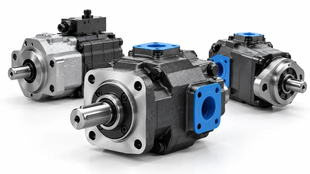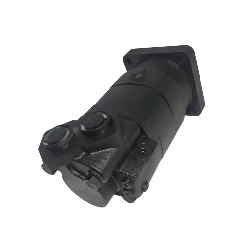
Most gear pump problems are decided in the enquiry rather than on the machine. A cylinder that moves too slowly on a cold morning, oil that climbs in temperature over a shift, a flange that will not line up with the bell housing: each one traces back to a number nobody wrote down when the pump was first specified.
Choosing a Hydraulic Gear Pump means matching four numbers to the machine instead of buying the largest unit that fits the space: the flow the actuators need, the continuous pressure the load demands, the displacement that produces that flow at the drive speed available, and the interface the equipment presents. Everything else, including noise, efficiency and service life, follows from those four decisions.
The sections below follow that order, because that is the order in which the decisions have to be made.
What a Hydraulic Gear Pump Has to Match on Your Machine
The duty defines the pump, not the pump’s maximum rating. Record five facts before comparing any catalogue page: the speed each actuator must reach, the force each one must produce, how many functions run at the same time, how long the machine works in a shift, and where the pump sits and what conditions it sees.
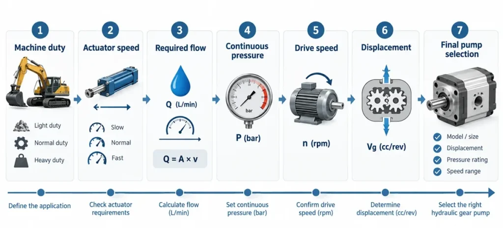
Those five inputs also decide whether a gear pump belongs on the machine at all. Two meshing gears trap a fixed volume of oil per revolution, so shaft speed sets the flow and downstream resistance sets the pressure. That suits a steady load but not circuits that run light all day with occasional bursts. ISO 4413, the general rules for hydraulic fluid power systems and their components, treats energy efficiency, reliable operation in all intended uses and maintenance economy as design obligations rather than refinements (ISO 4413:2010).
Where a Gear Pump Is Usually the Right Answer
Fixed flow at a steady load is the natural home of the gear pump, and the construction supports that role: few moving parts, no precision sliding surfaces, and tolerance for oil that is not laboratory grade. Power take-off circuits, loader hydraulics, single-ram power units and lubrication circuits all fit the pattern. The gear pump arrangement also keeps the unit compact and inexpensive to rebuild in the field.
Where a Gear Pump Is Not the Answer
There is no single best pump type. A gear pump stops being the right answer when the machine needs continuously high pressure, when flow must follow the load rather than the shaft speed, when a metering function needs very low pulsation, or when noise beside an operator is a design constraint. In those cases a piston or vane pump holds its efficiency where a gear pump is already losing volumetric efficiency to internal leakage, so the type comparison has to be settled before the construction is fixed.
Sizing a Gear Pump Step by Step: Flow, Pressure, Displacement, Speed
Size the pump from the actuator outward, never from the nameplate of the unit being replaced. Work out the flow from the fastest movement, set the continuous pressure from the heaviest sustained load, convert flow and drive speed into displacement, then check the drive can supply the power and torque required.
Step 1 Turn Actuator Speed Into Required Flow
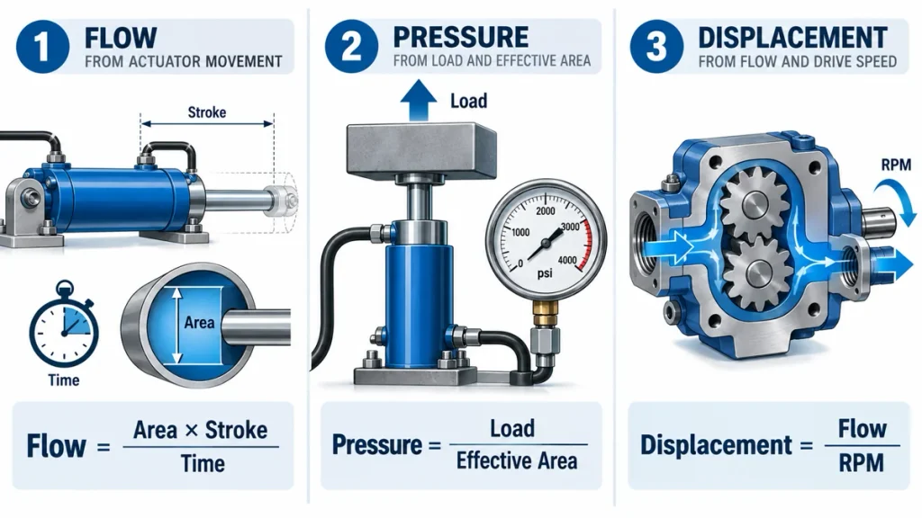
Flow, not pressure, decides how fast an actuator moves. Multiply effective piston area by stroke for the swept volume, divide by the movement time and convert to litres per minute using area in square centimetres x stroke in centimetres / time in seconds x 0.06. A 50 square centimetre piston with a 40 centimetre stroke sweeps 2 litres, so a movement that must finish in 5 seconds needs 24 litres per minute. Sum every function that runs at the same time rather than sizing on one actuator.
Step 2 Set Continuous Pressure and Peak Pressure Separately
Pressure comes from resistance, so it is calculated rather than chosen. Load force divided by effective area gives the working pressure: 20 kilonewtons acting on 50 square centimetres is about 40 bar. The relief valve setting is a different number, a ceiling reached during a stall. Size on the highest pressure the machine holds for minutes at a time, because a unit selected at its peak rating spends the rest of its life running hot.
Step 3 Convert Flow and Drive Speed Into Displacement
Displacement in cubic centimetres per revolution equals flow in litres per minute x 1000 / drive speed in revolutions per minute, so 24 litres per minute needs 16 cubic centimetres per revolution at 1500 revolutions per minute. Hydraulic power in kilowatts equals bar x litres per minute / 600, which makes 210 bar at 24 litres per minute about 8.4 kilowatts. Check the speed limits as well: below the minimum the surfaces are no longer lubricated, and above the maximum the inlet cannot fill the chambers.
| Quantity | How it is derived | What it decides |
| Flow required | Actuator area x stroke / movement time x 0.06, summed across simultaneous functions | Actuator speed and cycle time |
| Continuous pressure | Load force / effective area | Displacement rating and seal choice |
| Displacement | Flow x 1000 / drive speed | Model size and price band |
| Drive power | Bar x litres per minute / 600, plus losses | Motor or engine rating |
External or Internal Gear Pump: Choosing the Construction
Choose the construction from the duty rather than from habit. External gear pumps are the right default where oil cleanliness cannot be controlled, where first cost matters and where space is tight; internal gear pumps earn their price where low pulsation, lower noise and reliable running on thicker oil are requirements. Both are fixed-displacement, so construction changes how the flow is delivered, not how much of it.
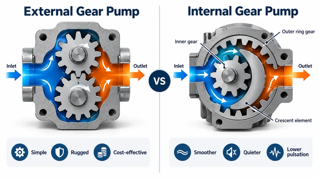
Internal pumps drive a larger outer ring with a smaller inner gear, with a crescent element sealing the two, so the ports open and close more gradually and pressure ripple falls. The trade is a tighter internal clearance, which demands cleaner fluid, and a higher price for the same displacement. An internal hydraulic gear pump built for precision industrial systems shows the logic clearly: the construction is bought for smoothness, not for pressure.
When an External Gear Pump Fits Better
Field-serviceable machines, contaminated environments and cost-sensitive mobile equipment point to an external hydraulic gear pump. Wider internal clearances tolerate particulate that would score a tighter unit, rebuilding is straightforward, and the cost per unit of displacement is the lower of the two.
When an Internal Gear Pump Fits Better
Internal construction is worth the premium when the operator sits close to the pump, when a metering function needs steady flow, when the circuit runs on high-viscosity oil or starts cold, or when noise accumulates across a continuous shift.
| Operating requirement | Better fit | Reason |
| Cleanliness cannot be controlled in service | External | Wider internal clearances tolerate particulate without rapid wear |
| Low sound level near an operator position | Internal | Gradual port opening and crescent sealing reduce pressure ripple |
| Cold start on high-viscosity oil | Internal | Stronger suction behaviour on thicker fluid |
| Steady flow into a metering or indexing function | Internal | Low pulsation delivery with no accumulator required |
Shaft, Mounting Flange, Ports and Rotation
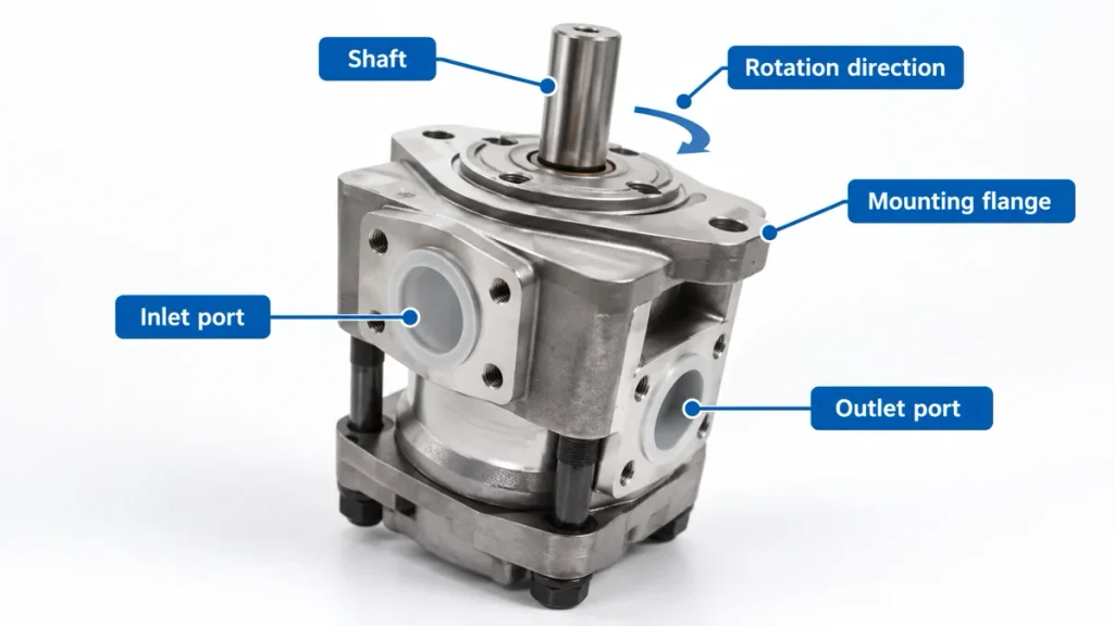
The mechanical interface is fixed the moment the order is placed and cannot be adjusted afterwards, so shaft, flange, ports, rotation and mounting position belong in the enquiry alongside the hydraulic figures. A pump with the right flow and pressure and the wrong pilot diameter or rotation cannot be adapted; it has to be replaced.
| Interface item | What to confirm | Consequence of a mismatch |
| Shaft | Type, diameter, key or spline, length | Coupling will not fit, or the shaft wears |
| Mounting flange | Bolt pattern, pilot diameter, bolt spacing | Pump cannot be aligned with the drive |
| Ports | Thread standard, size, and which port is suction | Wrong fittings, or a restricted inlet |
| Rotation | Clockwise or anticlockwise seen from the shaft end | Pump turns backward and damages itself |
| Mounting position | Above or below oil level, coupling type | Air entrainment, or a dry first start |
Multi-Section and Tandem Configurations
Where one machine drives several circuits, a single body with two or three sections costs less and takes less space than separate units, but the shaft carries their combined torque.
Fluid, Viscosity, Suction and Cleanliness
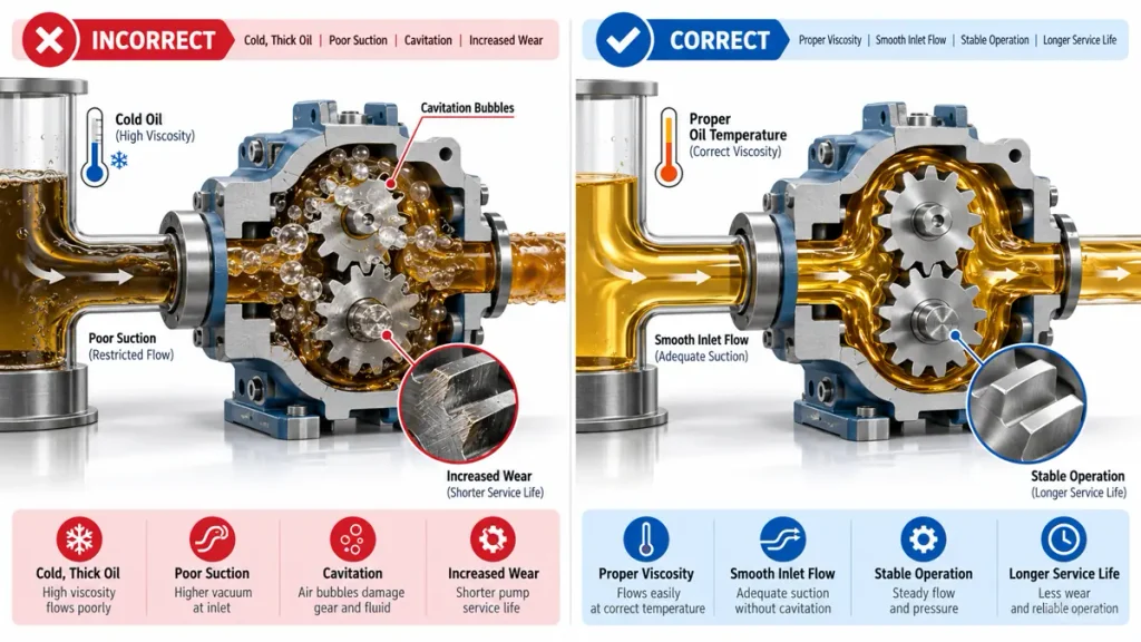
Fluid and filtration are sizing inputs, not housekeeping. A hydraulic gear pump that runs cool on 32 centistoke oil at working temperature will cavitate on that same oil at a cold start, leak more as the oil thins, and lose service life for every cleanliness code the circuit slips.
Viscosity Window and Suction Conditions
A practical working window for most gear pumps is roughly 16 to 40 centistokes at operating temperature, with a much higher cold-start limit read from the unit’s data sheet. Oil that is too thin increases leakage past the gears and the housing; oil that is too thick will not fill the chambers at speed, so the pump starves and cavitation damages the gear faces. Keep the inlet line short and generously sized, mount the pump below oil level where the layout allows, and check suction joints for air leaks.
Cleanliness Target at the Pump Inlet
A gear pump will run at around ISO 19/17/14 without rapid wear, which is why it survives on mobile equipment where tightly controlled fluid is unrealistic. The machine as a whole usually needs one or two codes cleaner, roughly 18/16/13 or better, because the valves and motors downstream are less tolerant than the pump itself. Filtration is normally split into a suction strainer, a pressure filter for the components downstream and a return filter that catches wear particles before they recirculate. ISO 4406 codes particle counts per millilitre at three sizes, so the target can be specified and measured (ISO 4406:2021).
Noise, Pulsation, Efficiency and Service Life
Noise, pulsation, efficiency and service life are outcomes of the selection, not settings that can be corrected later. A howling pump is usually a speed, displacement, mounting or suction decision, hot oil is usually a duty-cycle decision, and an early failure is usually a cleanliness decision.
Gear pump volumetric efficiency sits around 80 to 92 percent when the unit is new and inside its pressure band, and falls as pressure rises and clearances wear, because leakage past the gear tips becomes heat.
| What the operator notices | Typical selection cause | What to specify instead |
| Whine that rises with shaft speed | Displacement too small, so the unit runs faster than it should | Larger displacement at lower speed |
| Oil temperature climbing over a shift | Sized on the relief setting rather than sustained pressure | Size on continuous pressure, add an unloading path |
| Flow falling after one season | Cleanliness target set too loosely | Return filtration to the system target, not the pump target |
Checklist Before You Request a Quotation
Send the duty, not the part number. A supplier who receives the items below can propose a hydraulic gear pump and defend the choice; a supplier who receives only a model number is matching on price and hoping the rest lines up.
- The function the pump serves, and the type of machine it drives
- Required flow at each function, and which functions operate together
- Continuous working pressure, and the relief or peak pressure setting
- Drive type and available speed, whether engine, power take-off, gearbox or electric motor
- Displacement if known, or the flow and speed needed to derive it
- Shaft type, diameter and mounting flange pattern
- Port sizes, thread standard and required orientation
- Rotation direction and mounting position relative to the oil level
- Oil grade, viscosity at operating temperature and the coldest starting temperature
- Cleanliness target and the filtration already fitted to the machine
- Duty cycle, ambient conditions and the service interval expected of the machine
First-Start Checks That Decide Whether the Choice Was Right
Correct sizing shows in the first hour of running, not in the catalogue. Fill the case and suction line before the first start, check rotation before loading, and never run it dry. Watch case temperature, listen for a rising whine at working pressure, and inspect the return filter after the first shift. For a special build, the same points can be sent as a specification for a custom hydraulic pump built around the duty rather than adapted to it.
Frequently Asked Questions
The four questions below decide most disagreements about a specification: what the general rules of hydraulics actually require, whether one pump type can stand in for another, how an oversized unit can be proved rather than suspected, and how the right size is worked out in the first place.
What are the seven rules of hydraulics, and which ones govern gear pump selection?
The seven rules are a teaching summary rather than a numbered standard: pressure in a confined fluid acts equally in all directions; flow sets actuator speed while pressure sets force; pressure results from resistance rather than being set by the pump; hydraulic power equals pressure multiplied by flow; what enters a circuit must leave it, so simultaneous functions add their demands; losses become heat that has to be managed; and contamination is the leading cause of premature failure. Four decide a gear pump specification: flow continuity sets the flow figure, resistance sets the continuous pressure rating, the power relationship sets the drive and heat load, and contamination sets the cleanliness target.
Can a vane or piston pump be replaced with a gear pump on the same machine?
Sometimes, and the answer depends on three checks rather than on physical fit. Confirm that continuous working pressure sits inside the gear pump range, because a unit holding high pressure continuously runs hot and loses efficiency quickly. Confirm that the circuit does not rely on the pump changing its own output, since fixed displacement removes load sensing and pressure compensation. Then reset the relief valve to the new unit’s rating and recheck filtration and heat.
How do I tell whether a gear pump is oversized for the machine it drives?
Oversizing shows up as heat rather than as power. If a large share of the pump’s output is continuously crossing the relief valve at working pressure, that energy has become heat with nothing to show for it, and the oil temperature rise over a shift will confirm it. Two measurements settle the question: compare actuator cycle time against the duty requirement, and read flow in the relief return line while the machine works normally.
What size hydraulic gear pump do I need?
Size comes from four numbers: the flow the fastest actuator movement needs, the continuous pressure the heaviest sustained load needs, the drive speed available, and the displacement that follows. Displacement is flow in litres per minute times 1000 divided by drive speed, so 24 litres per minute at 1500 revolutions per minute lands near 16 cubic centimetres per revolution. Send those four figures to a gear pump manufacturer and the size follows.