A hydraulic piston motor is one of the highest-value rotating components in a fluid power circuit, and one of the least forgiving. Its internal clearances are machined to micron tolerances while it runs at full system pressure, so a developing fault shows up as lost production rather than an early warning. Having the service limits for the specific unit on hand makes the diagnostic work below far quicker.
The five problems behind most hydraulic piston motor downtime are overheating, fluid contamination, internal and external leakage, loss of speed and torque, and abnormal noise or vibration. Each has a distinct signature and can usually be narrowed down with external measurements before the motor is removed.
This guide covers each problem, then the shared root causes, the diagnostic sequence, and prevention.
What Are the Most Common Hydraulic Piston Motor Problems?
The five most frequent problems are overheating, fluid contamination, leakage, falling output speed and torque, and abnormal noise or vibration. Most begin as a slow change in one measurable parameter rather than as a sudden failure.
| Problem | Earliest symptom | First check |
| Overheating | Oil temperature rising at the same duty | Relief valve, case drain |
| Contamination | Gradual efficiency loss over hundreds of hours | Fluid sample, filter |
| Leakage | Drift, or oil at the shaft seal | Case drain flow and pressure |
| Loss of speed and torque | Slower cycle times under load | Flow at staged pressure |
| Noise and vibration | New or changed sound under load | Suction, alignment |
Two features explain why these five dominate. Clearances are held to very tight tolerances, so the motor is sensitive to any abrasive that reaches the loaded surfaces, and the pistons, cylinder block and running faces carry full system pressure, so a small loss of lubricating film escalates quickly into metal contact.
Where limits are documented by the Piston Motor Manufacturer, the checks below can be judged against real figures, and How Does a Hydraulic Motor Work covers how that pressure becomes rotation.
1. Overheating and Thermal Breakdown
Overheating is both a failure and an accelerator of every other problem here. If a piston motor runs hotter than it did on the same duty, treat it as a symptom and find the source rather than adding cooling capacity.
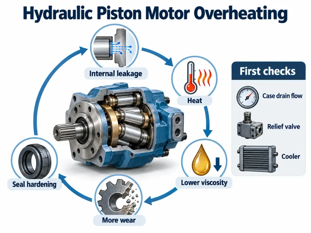
Heat matters because of the feedback loop it creates. Internal leakage converts pressure energy into heat instead of torque, and that heat thins the fluid, increasing leakage further. Thinner fluid also carries a weaker film, so wear accelerates and opens the clearances again.
How to Decide Whether the Temperature Is Actually Abnormal
There is no universal temperature limit. The permissible window depends on the fluid grade, additive package, duty cycle and ambient conditions, and the maker’s documentation governs. What is reliable is the trend on one machine: a motor that once stabilised at one temperature and now stabilises higher, at the same duty, has developed a problem. Fluid service life is commonly quoted as halving for every ten degrees Celsius above the recommended limit, but that is not a pass-or-fail threshold.
What to Check, in Order
- Establish where the heat is measured. Reservoir fluid, case drain fluid and housing skin are three different readings, and the maker’s limit applies to one specific measurement point. Record which point is used and measure there every time.
- Confirm the relief valve setting. A valve set or drifting low dumps flow continuously and generates heat with no work done.
- Measure case drain flow. Rising case drain flow means rising internal leakage, the most common internal heat source in the motor itself.
- Check the case drain line and the heat rejection side. A restricted case drain holds pressure in the housing, adding heat and loading the shaft seal, and a fouled cooler that is undersized for the duty is a common reason a system that used to run cool no longer does.
- Check the reservoir. Fluid volume and surface area are part of the heat balance, and a reservoir too small for the duty, or running low, holds heat the cooler alone cannot remove.
2. Fluid Contamination and Internal Wear
Fluid contamination is one of the leading causes of premature piston motor wear and failure. It is destructive because the particles that do the damage are too small to see, and because a piston motor depends on very fine running clearances.
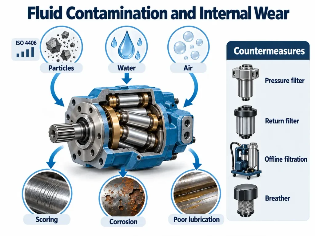
Particles caught in the running clearances score the loaded surfaces and widen the gaps on which efficiency depends, while water corrodes those surfaces and air lowers fluid stiffness. Each needs a different countermeasure, which is why treating contamination as simply dirt leads to fixes that do not hold.
The Three Contaminant Families
Solid particle cleanliness is reported using the standard on coding the level of contamination by solid particles, ISO 4406, which gives particle concentration at three size thresholds as a cumulative three-number code; the current version is ISO 4406:2021. It does not describe water or air, both measured separately and both capable of destroying a motor on their own, so a circuit can show an excellent code and still be failing from water. New oil may not meet the required level either, so pre-filtering before it reaches the reservoir is routine practice.
| Source | How it reaches the motor | Countermeasure |
| Ingressed particles | Breathers, worn seals, service openings | Desiccant breather, sealed transfer |
| Water | Condensation, breathers, wash-down | Breather upgrade, drainage, oil analysis |
| Entrained air | Suction leaks, low level, return above oil line | Seal suction, submerge returns |
| Internally generated | Component wear feeding further wear | Kidney-loop or offline filtration |
Filtration is layered rather than single-stage. A return-line filter protects the reservoir, a pressure-line filter protects components downstream of the pump, and an offline kidney-loop circuit cleans the fluid while the machine is idle. Element condition matters as much as specification, because a clogged filter goes into bypass. A Piston Pump Manufacturer on the same circuit should state the same requirements for the supply side.
3. Internal and External Leakage
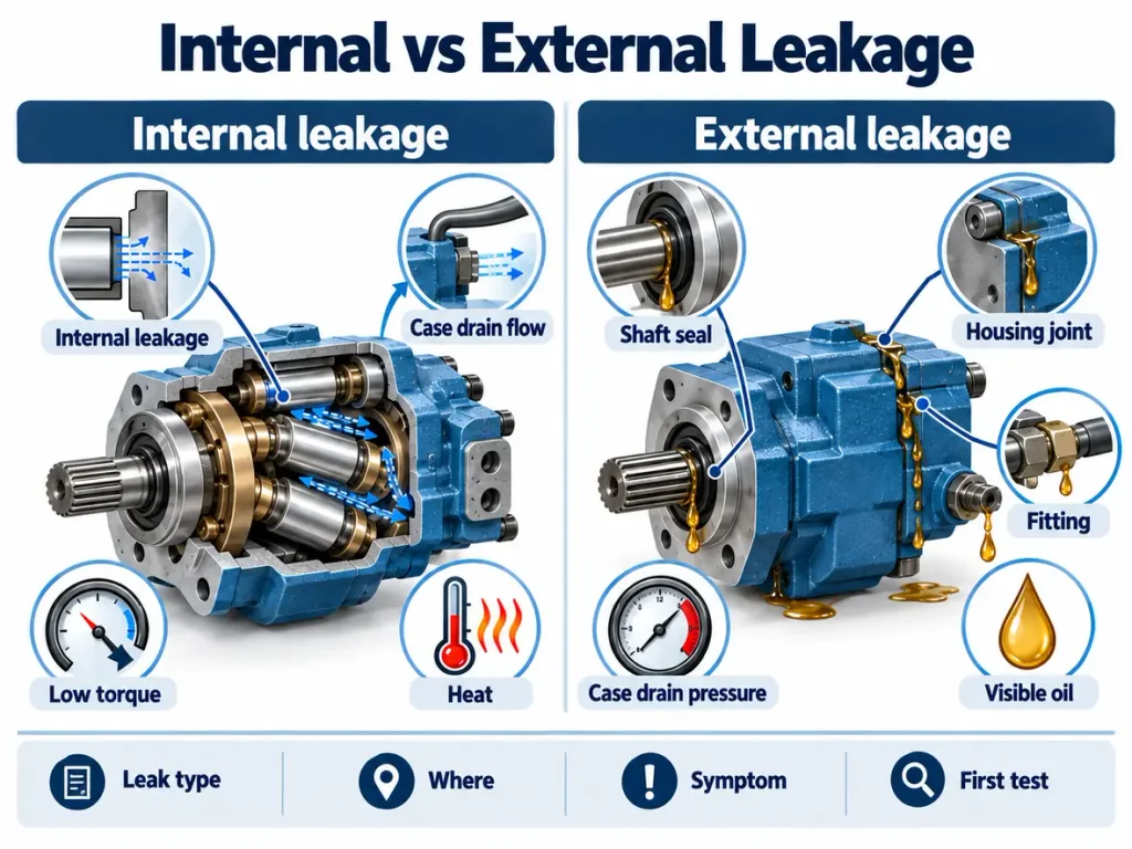
Internal and external leakage are two different faults with different symptom sets, and confusing them leads to replacing the wrong component. Internal leakage costs performance while the motor still looks dry; external leakage is visible but may not yet have cost measurable performance.
| Leak type | Where it occurs | Symptom | First test |
| Internal | Piston-to-bore, porting face, running faces | Falling speed and torque, hot fluid, drift | Flow at staged pressure |
| External | Shaft seal, housing joints, fittings, hoses | Visible oil loss, wet housing, low reservoir | Visual check, drain pressure |
Internal Leakage and Case Drain Flow
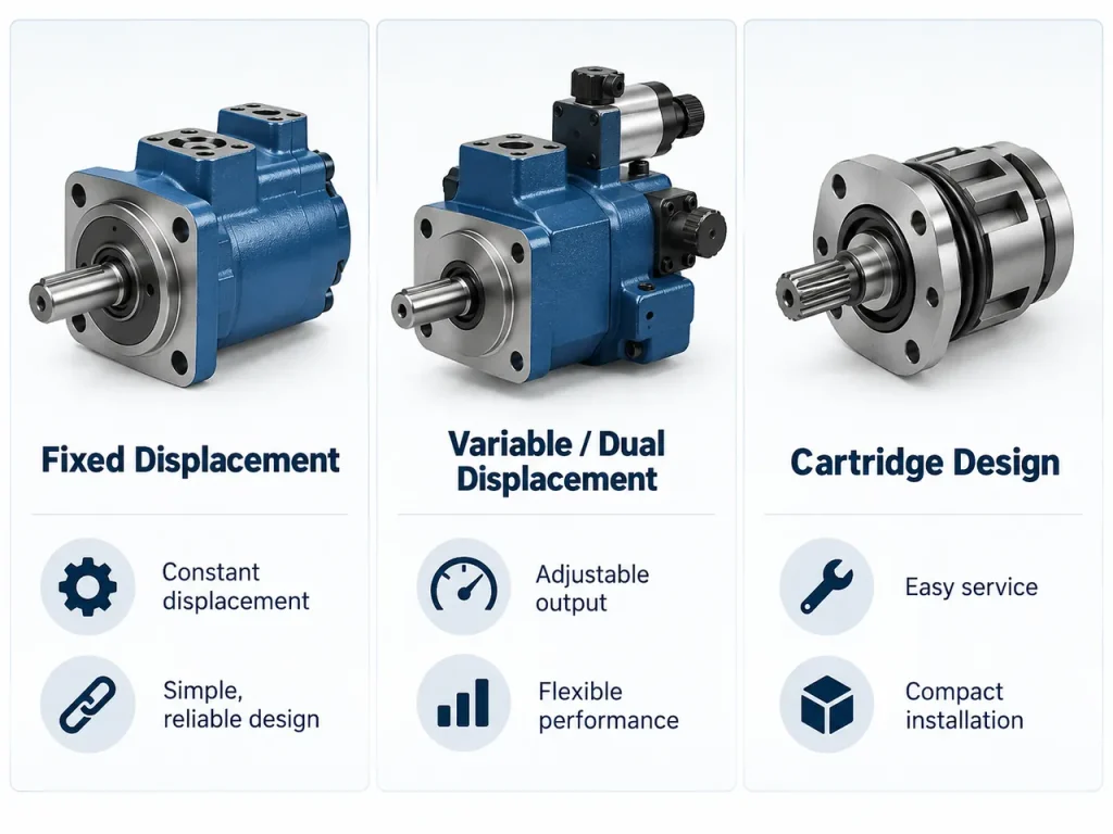
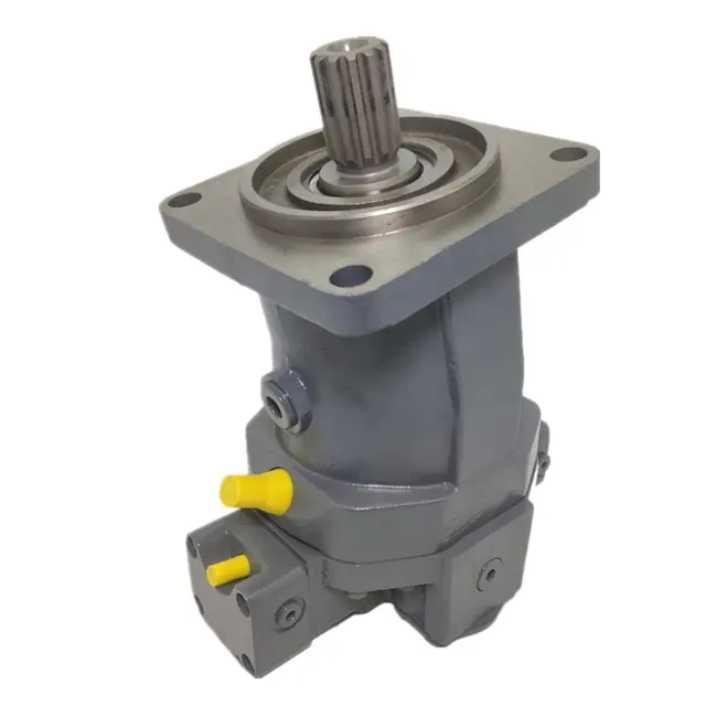
A proportion of the supplied fluid always bypasses the working elements internally, so most piston motors in industrial and mobile service are fitted with a case drain connection, as shown by this Fixed Displacement Axial Piston Motor. The arrangement is not identical on every unit: whether a separate drain port exists, which port it is, the permitted pressure and the connection requirements are all set by that motor’s documentation, and some designs route leakage differently. What matters is the trend. Case drain flow that has risen at the same conditions points to increased internal leakage, usually from wear on the piston group or running faces, but one high reading does not prove damage, since it varies with pressure, speed and temperature.
External Leakage and Case Drain Pressure
The shaft seal is the usual location for external leakage, and excess case drain pressure is one of the main reasons it fails. If the case drain line is undersized, restricted, or routed where it meets system back pressure, pressure builds in the housing, and once the seal’s limit is exceeded it is pushed out or washed away. Check the line for kinks before replacing the seal, and confirm the permitted pressure against the motor’s own documentation rather than a general figure.
4. Loss of Speed, Torque, and Efficiency
This section covers measuring and interpreting performance loss rather than its causes. Falling output is the measurable consequence of the faults already described, and the pattern across readings identifies which fault is present.
Performance in a hydraulic piston motor can only be judged when speed, torque and pressure are read together, since one symptom can come from different faults. Compare controlled readings against the curve for the rated displacement.
Reading the Symptom Pattern
| Pattern | Likely explanation | Confirm with |
| Speed falls as fluid warms, torque holds | Rising internal leakage, temperature dependent | Case drain flow trend |
| Speed and torque low at all temperatures | Clearance wear or capacity shortfall | Flow at staged pressure |
| Torque collapses before speed | Pressure loss upstream of the motor | Differential pressure |
| Speed low, pressure normal, no heat gain | Supply flow shortfall, not a motor fault | Pump delivery, valve setting |
The key measurement is a staged pressure and flow test, and it is only meaningful if four quantities are recorded at each step rather than flow alone.
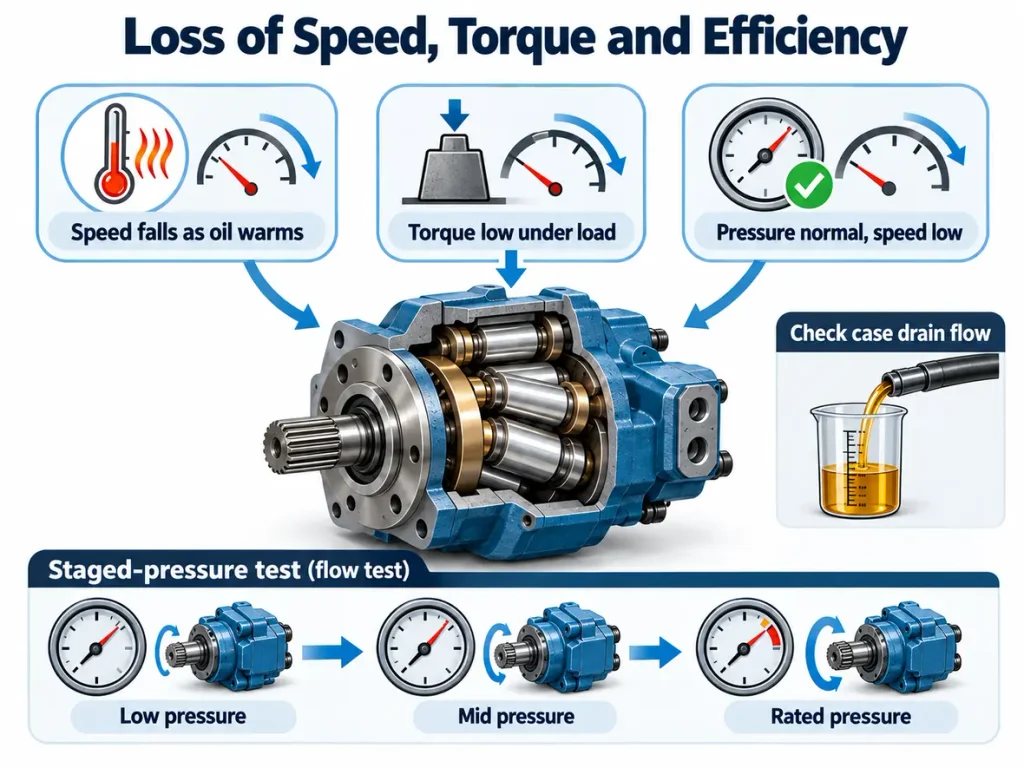
Record the flow delivered to the motor, the shaft speed, the differential pressure across it, and the case drain flow, all at the same moment. Differential pressure is the difference between inlet and outlet and corresponds to output torque, so total inlet pressure can look healthy while the differential falls. Shaft speed matters because flow and speed together give volumetric efficiency, and a motor losing speed while flow held steady tells a different story from one losing both.
Hold the test conditions steady. Bring the fluid to normal operating temperature before the first reading, because cold results are dominated by viscosity and cannot be compared with the curve. Keep inlet temperature within a narrow band, hold a constant load or speed as the procedure requires, and note speed and temperature with every reading. Step from a low proportion of rated pressure through half and full rated pressure, then repeat to confirm the numbers hold.
A healthy motor loses a small, predictable amount of flow as pressure rises, because leakage rises with pressure, and its speed holds against the curve. A worn motor loses flow steeply, its case drain flow climbs faster than the curve predicts, and the gap widens at operating temperature. A Variable Displacement Axial Piston Motor must be held at a fixed displacement for the comparison to mean anything. These readings can normally be taken with the motor in place, and if pump capacity is also in question, review the working principle in the Hydraulic Piston Pump guide before condemning the motor.
5. Abnormal Noise and Vibration
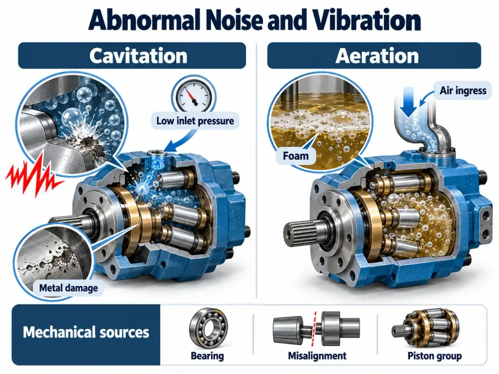
Noise in a piston motor is a fingerprint rather than a fault code. The character of the sound points to its source, and separating fluid-borne noise from mechanical noise is the first useful step.
| Sound | Likely source | First check |
| High-frequency rattle or whine | Cavitation or aeration | Suction line, oil level, viscosity |
| Grinding or rumbling | Bearing wear or contact | Bearing condition, alignment |
| New tone tied to rotation speed | Wear in the rotating group | Case drain flow, performance test |
Cavitation Versus Aeration
These two are often treated as one problem and they are not. Cavitation happens when inlet pressure falls below the vapour pressure of the fluid, so bubbles form and collapse violently against metal surfaces, eroding them. Aeration happens when air is drawn in on the suction side, lowering fluid stiffness.
Whether the noise disappears when the load is removed is a weak indicator on its own, because an aerated circuit can also quieten once unloaded and a lightly loaded cavitating circuit can stay noisy. Use several signals instead. Record inlet pressure at the motor: pressure that falls with flow points to inlet restriction or starvation rather than entrained air. Check the reservoir for foam or milky fluid and whether the level keeps the return line submerged, both of which point to air drawn in or held in suspension. The system conditions point the same way: a cold start on a high-viscosity grade, a clogged suction strainer, an undersized suction line or operation above rated speed favour cavitation, while a loose suction fitting, a low reservoir level or a return discharging above the oil line favour aeration. The corrective actions differ, so establish which condition the readings support before adjusting anything.
Alignment, Mounting and External Mechanical Sources
Mechanical noise does not always come from inside the motor, and misalignment and mounting problems should be ruled out before the unit is stripped. A coupling out of alignment loads the shaft bearings, works the shaft seal and produces a tone that rises with speed. A base that flexes under load lets the motor move as torque is applied, changing alignment dynamically even when it was correct at rest, and rigidly connected, unsupported pipework can transmit resonance into the housing. Check coupling alignment against the maker’s tolerance, confirm the mounting face is flat, and check the base is rigid enough for the applied torque.
Noise From the Rotating Group
Mechanical noise that tracks rotation speed, worsens under load and survives the checks above usually originates in the rotating group or its bearings, and the arrangement depends on the design. In swashplate axial motors the pistons act against an inclined plate and the running surfaces include slippers and a porting face; in bent-axis designs the cylinder block itself is inclined; in radial motors the pistons act outward against a cam ring or eccentric. Slipper and swashplate wear, or porting face scoring, are specific to particular axial designs rather than generic piston motor faults. A new tone with falling speed and rising case drain flow points to wear in the loaded interface, whichever one that design uses.
What Are the Common Causes of Piston Motor Failure?
Almost every piston motor failure resolves to one of a small number of root causes, and identifying the cause determines whether it will recur. A motor replaced for wear without the cause being addressed will wear again at the same rate.
Failure of the Piston Group Itself
Wear inside the piston group is distinct from the system-level causes below, and it is the finding that most often decides whether a hydraulic piston motor can be repaired. In axial designs, whether swashplate or bent-axis, the loaded interfaces are the piston-to-bore pair, the running face between the piston assembly and the inclined plate, and the porting face that distributes flow from the cylinder block. In radial motors the loaded surfaces are the piston-to-bore pair plus the cam ring or eccentric contact.
The damage follows a predictable pattern. Clearance opens between piston and bore, so internal leakage rises and the motor loses speed and torque progressively rather than suddenly. The running faces at the inclined plate or cam ring lose their film under load and begin to score, accelerating wear and adding a tone that tracks rotation speed. Because these surfaces are matched during manufacture, wear beyond the maker’s limits means machining and re-matching the group as a set rather than replacing a single part, and this finding more than any other turns a seal-and-bearing repair into a replacement.
System-Level Root Causes
| Root cause | How it damages a piston motor | Preventive action |
| Fluid contamination | Particles score loaded surfaces; water corrodes and strips additives; air lowers stiffness | Filtration, sampling, breather upgrade |
| Sustained high temperature | Oxidation and varnish, hardened seals | Fix the heat source first |
| Incorrect viscosity | Thin fluid leaks internally, thick fluid starves the inlet | Verify grade against running temperature |
| Misalignment or soft mounting | Bearing load, seal wear, vibration | Realign, use a rigid base |
| Excess case drain pressure | Shaft seal failure, housing pressure rise | Verify case drain routing |
How to Troubleshoot a Hydraulic Piston Motor in Order
The correct order of work is to observe the symptom, check the simplest external causes, then measure pressure and flow, and only then remove the motor. Following that sequence keeps the most expensive step last.
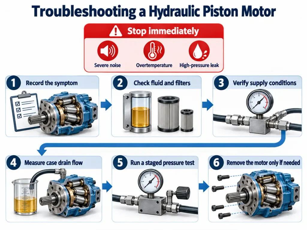
Safety governs the sequence as much as cost does. Before any check on a live circuit, confirm it can be isolated; before any load test, confirm it can be depressurised and that stored energy in accumulators or suspended loads has been released. The general rules are set out in the standard on general rules and safety requirements for hydraulic fluid power systems.
- Record the symptom precisely. Note when it appears, at what load, at what fluid temperature, and whether it is constant.
- Check the fluid and filters first. Level, condition, colour and element condition are external, fast and often decisive.
- Verify supply conditions. Confirm pump delivery, relief valve setting and filter bypass before blaming the motor.
- Measure case drain flow and pressure. Compare against commissioning values and maker’s limits, reading the two separately.
- Run a staged pressure flow test. Step from low to rated pressure, watching flow loss and case drain flow together.
- Remove the motor only when external evidence points inside it. The readings then show what to look for.
Stop and isolate immediately, rather than continuing a loaded test, if a severe change in noise occurs, if there is any sign of internal jamming, if fluid temperature rises past the maker’s limit, or if a high-pressure leak or spray appears. A pressurised leak is a serious injection hazard, and a motor suspected of internal jamming should not be run under load for more data.
How to Prevent These Problems
Prevention is a duty-based programme rather than a calendar one. The right inspection frequency depends on running hours, the working environment, and what the motor and system makers specify.
Fluid and Filtration Discipline
Sample the fluid on a fixed interval and trend the results rather than reacting to a single report. Maintain filtration at the cleanliness target the most sensitive component requires, and keep the breather in good condition, since a contaminated breather undoes months of fluid management in a shift.
Operating Within Rated Limits
Keep continuous pressure, peak pressure, speed and fluid temperature inside the limits stated for the motor. Verify the case drain line is correctly sized and routed so housing pressure stays in the permitted range, since this governs shaft seal life. Where the motor supports displacement switching, confirm it happens within the conditions the maker allows, since performance depends on the switching ratio, duty and speed limit.
Inspection and Condition Monitoring
| Check | Interval basis | Trigger for action |
| Fluid sample and trend | By running hours and duty; shorten it in dusty, humid or high-duty environments | Cleanliness or water content outside the target set by the most sensitive component |
| Filter element condition | Each service interval, or continuous differential monitoring | Differential approaching the bypass value, or a rising trend at constant duty |
| Case drain flow and pressure | Record at commissioning, then at every planned stop at the same pressure and temperature | Flow trending up at constant conditions, or pressure above the motor’s maximum |
| Noise and temperature baseline | Record while healthy, then compare at every planned stop | Any new tone, or a higher steady-state temperature at the same duty |
| Fluid and filter change | Per the maker’s schedule for the fluid and duty, supported by sample results | A sample result, not elapsed time, showing the fluid no longer meets the required cleanliness |
Recording a baseline while the motor is healthy is the most useful maintenance action available, and where a circuit is being specified rather than maintained, a Custom Hydraulic Motor built to the duty avoids several mismatches above.
Frequently Asked Questions
How do I know whether to repair or replace a hydraulic piston motor?
Repair is usually better when damage is limited to seals, bearings or the shaft seal and the loaded interfaces remain within tolerance, since those are replaceable items. Replacement becomes better when the piston group, running faces or porting face are worn beyond the maker’s limits, because restoring them means machining and matching components as a set. The deciding evidence is the strip-down inspection supported by the case drain flow trend and the staged flow test, not the age of the motor.
Can a hydraulic piston motor run in reverse without damage?
Many piston motors are designed for flow and rotation in both directions, but that is not universal. Safe reverse operation depends on the model, on whether the case drain arrangement and porting suit bidirectional service, and on the pressure protection on what becomes the inlet side. Check the maker’s documentation before relying on it, and never reverse a motor not rated for it.
What cleanliness level should the fluid in a piston motor circuit meet?
No single figure applies to every piston motor circuit. The target is set by the most contamination-sensitive component, which in a piston motor circuit is often a servo or proportional valve rather than the motor itself. Obtain the target from that component’s maker and design filtration to it. ISO 4406 reports the solid particle result at three size thresholds and should be read alongside separate water and air measurements.