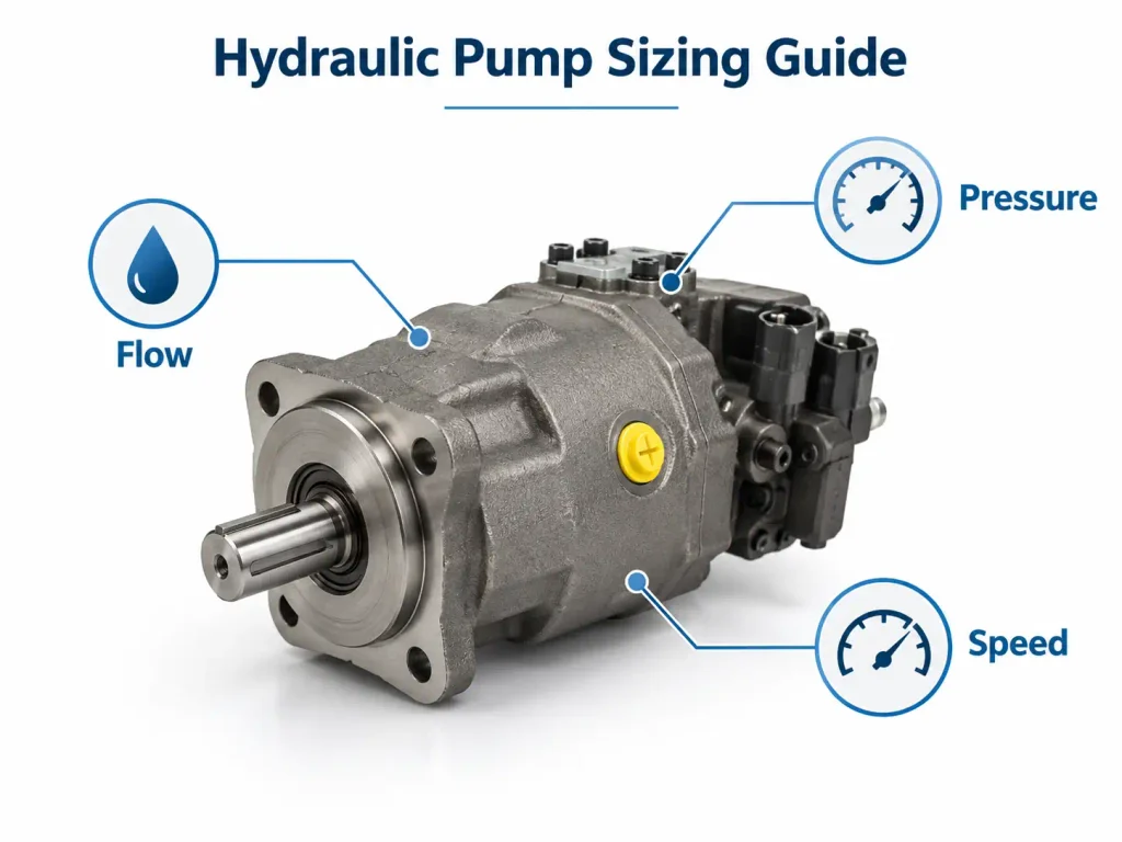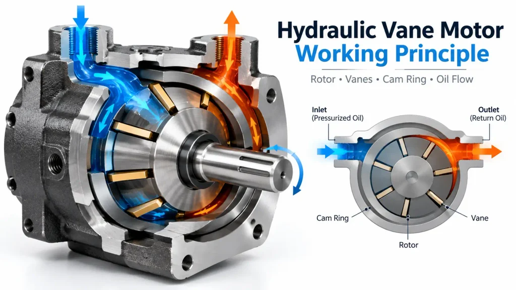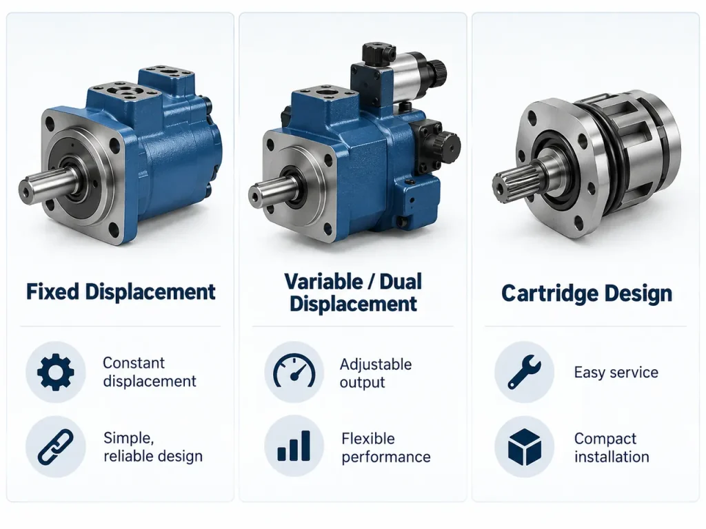
Heavy-duty hydraulic machinery often needs high starting torque, controlled rotation and reliable performance under changing loads. Gear and vane motors serve many applications economically, while piston motors are chosen when higher pressures, power density or precise control are required. Buyers comparing motor options therefore need to understand how piston motor designs differ and which conditions justify their extra cost, so they compare the piston motor ranges a Piston Motor Manufacturer publishes.
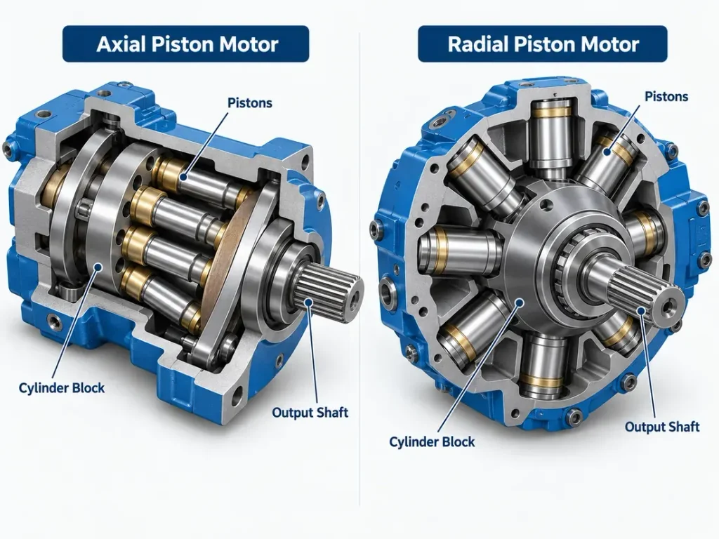
A hydraulic piston motor is a rotary hydraulic actuator that converts the pressure and flow of hydraulic fluid into torque and rotation using pistons that reciprocate inside cylinder bores. Axial piston motors arrange the pistons along the cylinder block axis, and radial piston motors arrange them radially around it.
The sections below explain how that conversion works, how the types differ, and where the design earns its cost.
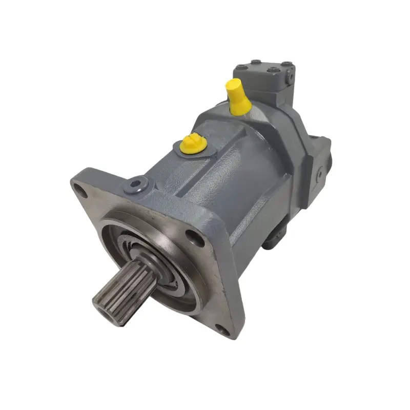
What Is a Hydraulic Piston Motor?
A hydraulic piston motor is a positive-displacement motor in which pistons travelling in individual cylinder bores turn hydraulic pressure into mechanical force, and a conversion mechanism turns that force into shaft torque. Every piston motor follows this path; the designs differ in how the force reaches the shaft.
The piston type reaches positive-displacement conversion through a precision piston-to-bore mechanism and a distribution structure that admits and discharges fluid as it rotates. Piston and bore form a controlled clearance rather than a perfect seal, so a small internal leakage path always remains, and its size depends on clearance, pressure, viscosity and wear. Many piston motor models are built for higher working pressures and return higher efficiency than gear or vane designs. The pistons are the internal components that convert hydraulic pressure into mechanical force, which the motor mechanism then transfers into rotation.
The conversion runs in reverse of the one performed by a piston pump, which is why the two share much internal geometry. A piston motor also belongs to a wider family, since a Hydraulic Motor Manufacturer normally offers gear, vane, orbital and piston types side by side; the piston type is specified when pressure, efficiency and control tolerance allow little compromise.
How a Hydraulic Piston Motor Converts Pressure into Torque
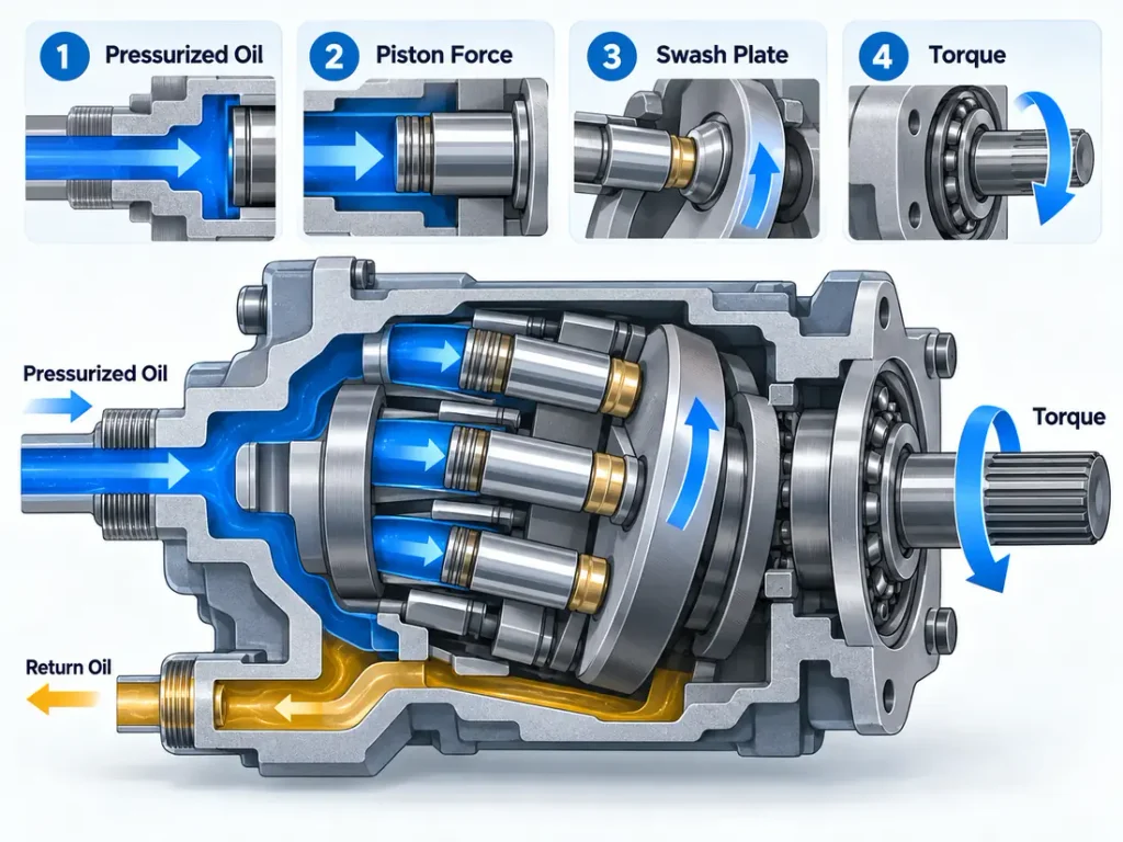
Pressurised hydraulic fluid enters the working chambers through a distribution mechanism. The resulting piston force is converted into shaft torque by a swash plate, bent-axis assembly, eccentric shaft, or cam mechanism, depending on the motor design.
In a swash-plate motor the pistons push against a tilted surface, and the tangential component of that reaction rotates the cylinder block. In a radial motor the pistons push outward, so a separate cam or eccentric geometry supplies the tangential component. Rotation direction is a specification rather than a given: for a motor rated for bidirectional operation, reversing the hydraulic flow can reverse the output shaft, but only models that declare the capability, with a matching circuit, behave that way.
Types of Hydraulic Piston Motors
Hydraulic piston motors divide along two independent dimensions: piston arrangement, separating axial motors, with the pistons arranged along the cylinder block axis, from radial motors, with the pistons arranged radially around it, and displacement control, separating fixed, dual and variable designs. A single motor holds one setting on each dimension.
Arrangement decides where torque is produced and how the package is shaped; displacement control decides whether output can be adjusted while running.
Axial Piston Motors: Swash Plate and Bent Axis
Axial piston motors arrange the pistons along the cylinder block axis and use either a swash plate or a bent-axis geometry to turn piston stroke into rotation. In swash-plate designs the cylinder block and output shaft are generally aligned, while bent-axis designs incline the cylinder block to the drive shaft. They are generally the compact, high-speed end of the family, chosen where power density and control matter.
In the swash-plate version the cylinder block rotates with the shaft while a tilted plate stays fixed, and the swash plate angle sets piston stroke and therefore displacement.
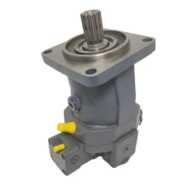
In the bent-axis version the block is inclined to the drive shaft, creating a different force-transmission path, and the pistons drive through rods rather than sliding shoes. Side loads are lower, but the variable range and any weight penalty vary between series rather than applying to every bent-axis design. A Bent-Axis Piston Hydraulic Motor of this kind suits a mobile machine needing a wide speed range in a closed circuit.
Radial Piston Motors: Cam Ring and Crankshaft
Radial piston motors arrange the pistons radially around the shaft, converting piston thrust into rotation through either a cam ring or an eccentric crankshaft. The layout produces very high torque at low speed, so these motors often drive a load without a reduction gearbox.
In a cam-ring motor the pistons act against the inner flank of a cam, and each lobe adds a working stroke per revolution, which is how a compact frame reaches a large displacement without growing its envelope. In a crankshaft motor each piston drives through a connecting rod onto an offset journal, and the single large eccentricity gives very high peak torque per piston. Because at least one piston produces torque at every instant, output stays continuous rather than arriving as separate pushes. That continuity lets the motor start a loaded winch or a stalled conveyor without a clutch, and it is why the housing carries large radial loads.
Fixed, Dual and Variable Displacement Piston Motors
Fixed motors hold one displacement, dual motors switch between two, and variable motors adjust displacement through a mechanism while running. Only the variable type gives stepless control of the torque and speed relationship.
A fixed-displacement motor has one displacement, so speed follows flow and torque follows pressure differential. A dual-displacement motor operates at two discrete settings. At reduced displacement it runs faster at the same flow while producing less theoretical torque at the same pressure; if displacement is halved, ideal speed doubles and ideal torque halves, while other ratios give different results, and actual performance depends on efficiency and the manufacturer’s operating limits. It is not continuously variable, because it switches between two values instead of sweeping a range. A variable-displacement motor moves displacement through a control mechanism, so the torque and speed relationship is trimmed to the duty while running.
How Piston, Slipper and Roller Designs Affect Performance
The piston end carries a contact or force-transfer element whose design varies with the mechanism, and friction, lubrication, contact stress, wear and running smoothness follow from that choice.
Sliding-shoe designs spread load across a larger area and support a fuller lubricating film, while some bent-axis designs transmit force through a rod or ball joint. Radial motors commonly use rollers against a cam or eccentric surface, cutting sliding and improving starting. The trade-off is the same everywhere: a larger, better-lubricated contact tolerates more load and lasts longer, while a smaller contact reduces friction and inertia but needs cleaner fluid.
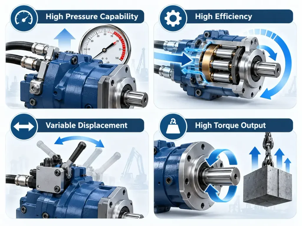
Key Benefits of a Hydraulic Piston Motor
Many piston motor designs deliver more torque per unit of size, at higher pressure and with better efficiency than a comparable gear or vane motor, and displacement can often be adjusted while running. That is why the type is specified where duty is severe or control demand is tight.
| Benefit | What It Means for Machinery | Performance Indicator |
| High pressure capability | Delivers power within a compact drive | Rated pressure |
| High efficiency | Reduces hydraulic power losses | Overall efficiency |
| Variable displacement | Extends the usable operating speed range | Displacement range |
| High torque output | Handles demanding loads without a gearbox | Rated and starting torque |
The indicator names above are the figures to request, not interchangeable values: they differ between series and are quoted at defined test conditions, so read them from the intended model’s data sheet.
Power Density and Pressure Capability
A piston motor turns a small envelope into a large turning moment because pressure acts over a defined piston area inside a compact housing. Raising that pressure is the most direct way to gain torque without enlarging it, which is why the piston type sits near the top of the pressure range. The limit lies in the components, because higher pressure increases the load on every sliding and rolling contact.
Efficiency and Precise Speed Control
Efficiency in a hydraulic motor splits into volumetric and mechanical parts. Many piston motor designs keep internal leakage low and their low-friction contacts limit mechanical loss, so more hydraulic power reaches the shaft. Variable displacement adds a second option: speed and torque can be regulated by changing displacement rather than throttling flow, which reduces the energy lost as heat, although the saving depends on how the whole hydraulic system is controlled rather than on the motor alone.
Starting Torque and Low-Speed Smoothness
Starting torque and low-speed behaviour are not family-wide properties; they depend on the arrangement and the model.
Radial piston motors are the arrangement most commonly built for this duty. Their large displacement and long moment arm produce high starting torque from standstill, they hold that torque at very low speeds, and the multi-piston layout overlaps each piston’s contribution to keep output smooth, so many designs drive a winch or wheel without a gearbox. Axial piston motors are often chosen instead for high power density, a broad speed range and precise control. Some specialised axial piston motors are also engineered for high starting torque and smooth low-speed operation, so performance should be judged by the specific motor configuration and published operating data rather than piston orientation alone.
Limitations and What to Watch For
A piston motor costs more, tolerates contamination less and is bulkier than a gear or vane motor of similar output, so it is not specified everywhere.
The main limitations are:
- Higher purchase price and repair cost, because the precision parts are matched and cannot always be replaced individually.
- Sensitivity to fluid contamination, since small clearances and thin lubricating films are what keep the motor efficient; vane motors also depend on clean fluid, as contamination damages their porting surfaces and accelerates wear.
- Greater mass and envelope, particularly in radial designs whose housings carry large radial loads.
Fluid Cleanliness, Case Drain and Heat
Cleanliness class, permissible case pressure, case drain arrangement and temperature limits are specific to the series and must be read from that model’s technical manual rather than applied as a general rule for piston motors. The margins are small. Contamination a gear motor would tolerate can score a sliding surface, and the result is increased internal leakage with a slow loss of speed and torque rather than sudden failure. A rising case drain flow can point to internal wear, but only when read against comparable pressure, speed and temperature, because the same change means something different once the duty point has moved. Viscosity and temperature belong together, since the film protecting the contacts depends on both, and hydraulic fluid viscosity ties them together.
When a Piston Motor Is Not the Right Answer
Where duty is light and intermittent, the extra cost and the filtration discipline are hard to justify, and a simpler design usually delivers the required work for less. Gear motors and many vane and orbital motors are cheaper and generally more tolerant of contaminated fluid, and an orbital motor covers low-speed, high-torque duty at moderate pressure on a smaller budget. The choice is not about which type is better in the abstract but about which matches the pressure, speed, duty cycle and environment. Our comparison of the different types of hydraulic motors sets the four families against each other on pressure, speed, efficiency, contamination tolerance and cost.
Uses and Applications of Hydraulic Piston Motors
Piston motors appear wherever a machine must move a heavy load slowly and reliably, adjust speed over a wide range, or deliver high torque from a compact drive. The arrangement chosen follows the operating requirement, not the industry.
| Operating requirement | Suitable configuration | Main reason |
| Compact, high-speed hydraulic drive | Axial piston, especially suitable bent-axis designs | High power density and speed capability |
| Adjustable torque and speed operation | Variable-displacement axial piston motor | Adjustable displacement |
| Very high starting torque at low speed | Radial piston motor | High displacement and strong low-speed torque capability |
| Heavy-duty direct drive | Suitable radial piston motor | Can reduce the need for gear reduction |
These rows describe typical directions rather than absolute selection rules, and the final choice must be checked against the rated pressure, speed, torque and mounting conditions of the specific model.
Mobile and Construction Machinery
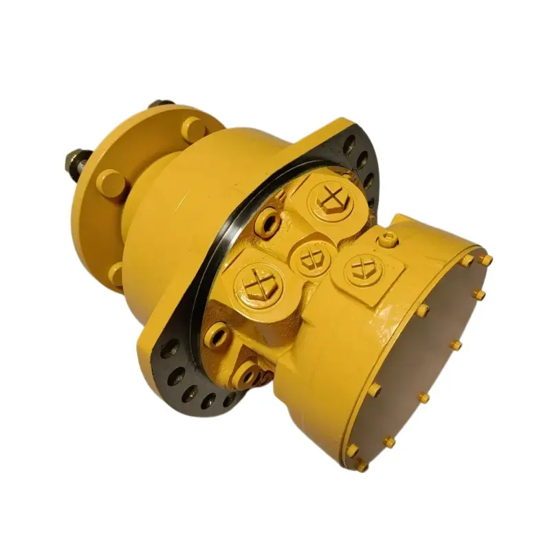
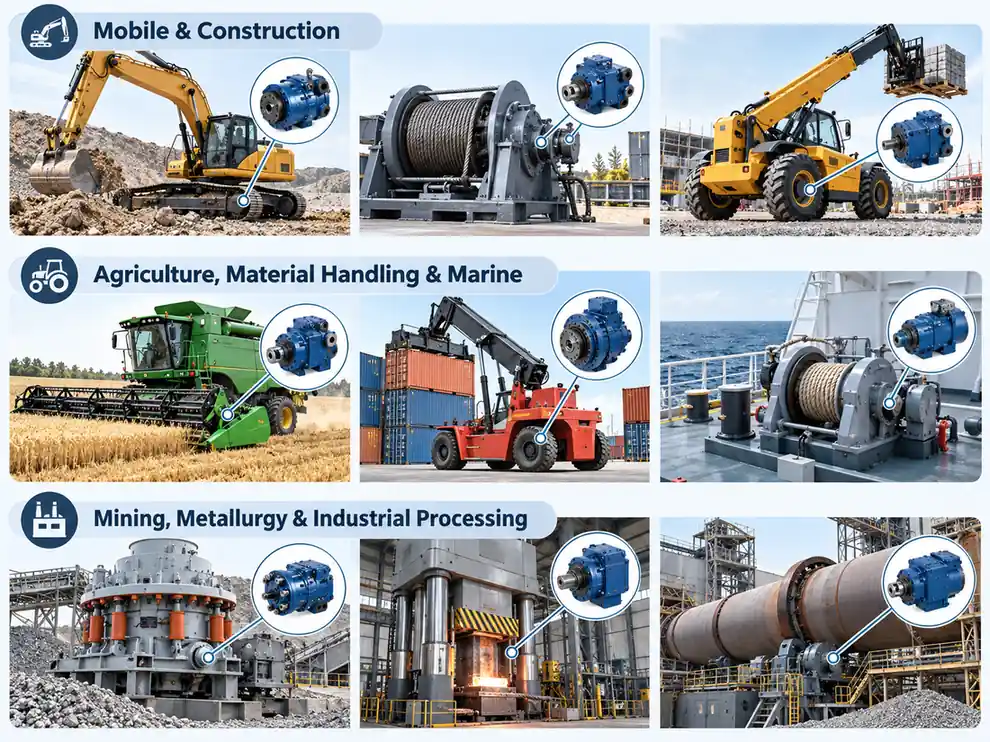
Hydraulic piston motors are widely used in construction machinery for travel, swing and auxiliary drives. Many excavator travel systems use axial piston motors with reduction gears and parking brakes, while selected swing, wheel-drive and winch applications use radial piston designs. The preferred configuration depends on starting torque, speed range and circuit layout. Wheel drives on haul trucks use a direct-drive Radial Piston Hydraulic Motor to remove the mechanical driveline, and cutter head drives on tunnelling machines rely on the same characteristic at low speed.
Agriculture, Material Handling and Marine
Harvesters, balers and spreaders use piston motors where torque is needed at low speed in dusty conditions and where a gearbox would add maintenance, and material handling equipment follows the same logic in loaders and conveyors. On vessels, deck machinery, anchor winches and towing gear need controlled movement of heavy loads at low speeds in a corrosive environment, while safe load holding always depends on a dedicated braking device rather than the motor itself.
Mining, Metallurgy and Industrial Processing
Crushers, drilling rigs and heavy conveyors in mining put the motor under continuous load, shock and contamination at the same time, so cleanliness discipline and case drain design decide service life. In metallurgy and processing, extrusion lines, presses, rotary kilns and drum drives use piston motors where a large turning moment is needed across a wide speed range.
FAQ
The questions below cover what buyers ask most before selecting a piston motor: rotation direction, load holding, and the first signs of wear.
Can a Hydraulic Piston Motor Run in Both Directions?
Only if the model is rated for bidirectional operation. Many piston motors are, and reversing the flow reverses the shaft, but the capability is declared per model and should not be assumed. The circuit has to match: the case drain, the return line and any brake or control valve must work in both directions within the stated limits.
Can a Hydraulic Piston Motor Hold or Brake a Load?
A hydraulic motor should not be relied on as a static load-holding device. Internal leakage past the pistons and through control valves lets a suspended load creep even when the motor is stopped, making it an unreliable brake for winches, hoists and lifting equipment. Where a load must be held safely or stopped under control, a purpose-designed mechanical brake and matching control valves are required, sized for the load.
What Are the Early Signs That a Hydraulic Piston Motor Is Wearing Out?
Increased internal leakage is one of the earliest indicators, and it appears as slower speed or reduced torque for the same flow and pressure rather than an outright failure. A rising case drain flow, a higher operating temperature, or new noise and vibration point the same way. The first check is a fluid sample at the normal duty point, then verifying case drain flow against the technical manual, because a symptom measured at a different pressure, speed or temperature can mislead.