Hydraulic motors sit at the output end of a fluid power circuit, where fluid pressure is converted back into rotation. Several mechanical arrangements can do this, so specifying a motor means trading efficiency, torque, speed, contamination tolerance, and cost against one another.
Hydraulic motors are grouped into four families by the working element that converts pressure into rotation: gear motors, vane motors, piston motors, and orbital motors. Gear motors are the simplest and least expensive and drive conveyors, fans, and auxiliary circuits. Vane motors run smoothly and quietly and suit machine tools, presses, and industrial machinery. Piston motors, divided into axial and radial designs, offer the highest pressure capability and efficiency. Orbital motors deliver high torque at low speed from a compact body and drive agricultural implements, augers, and wheel drives.
The sections below explain how each family works, where it is used, and how to match a type to a duty.
What Are Hydraulic Motors and How Do They Work?
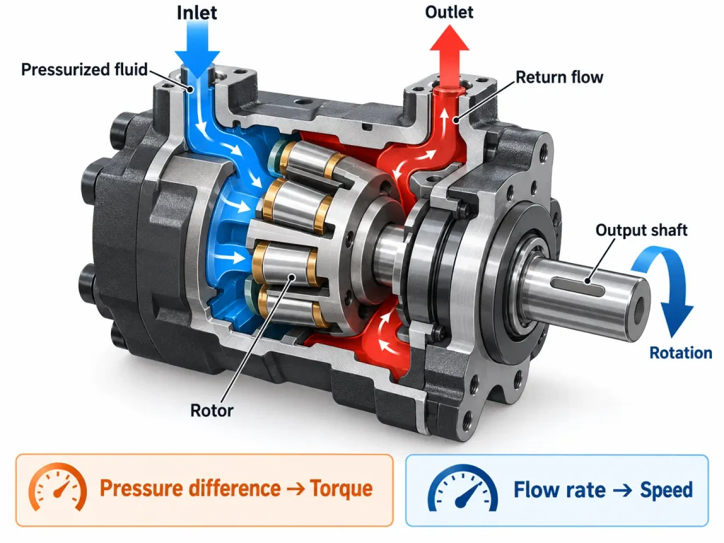
A hydraulic motor is a rotary actuator that converts hydraulic pressure and flow into torque and angular displacement. Fluid acts on a moving element, whether a gear tooth, a sliding vane, a piston, or the rotor of a gerotor set, and the resulting force turns an output shaft. Flow rate sets how fast the shaft turns, and pressure differential across the motor sets how much torque it can produce.
The motor is the rotary counterpart of the hydraulic cylinder, and neither creates pressure or flow of its own; the designer controls motor output through the pump and valves upstream.
How Hydraulic Motors Generate Torque and Speed
Torque depends on displacement, the volume of fluid required to turn the shaft once, and on the pressure differential across the motor. Speed depends on flow rate and the same displacement. Raising flow turns the motor faster without adding torque, and raising pressure adds torque without changing speed at a given flow.
Displacement therefore links the two: large displacement gives more torque per unit of pressure and lower speed per unit of flow, and small displacement does the opposite. This is why a Hydraulic Motor Manufacturer data sheet lists displacement, rated pressure, and maximum speed together with mounting pattern and shaft type.
Key Performance Factors
- Volumetric efficiency is how much fluid entering the motor becomes rotation rather than leaking past internal clearances, and it falls as pressure and wear increase.
- Mechanical efficiency is how much theoretical torque survives friction. Overall efficiency is the product, so ninety percent of each gives roughly eighty percent overall.
- Starting torque is the torque available from standstill, which is always lower than running torque, because sealing in several designs depends on a fluid film that develops only once the shaft turns.
- Minimum stable speed is the lowest speed at which a motor turns without stick-slip juddering.
Reference material on Hydraulic motor operation confirms this definition and adds one structural difference that matters: a motor must accept flow in either direction and produce useful torque from standstill.
What Are the Different Types of Hydraulic Motors?
The four types of hydraulic motors are gear motors, vane motors, piston motors, and orbital motors, distinguished by the working element that receives the fluid pressure. That element sets the pressure the motor accepts, the speed range it delivers, its efficiency, and its tolerance of contaminated fluid. Gear and vane motors occupy the economical high-speed end of the range, axial piston motors the high-pressure and high-efficiency end, radial piston motors the extreme-torque and very-low-speed end, and orbital motors the compact low-speed high-torque middle ground.
Classification here follows how the market groups these products rather than a strict separation of machine principles: orbital and internal gear motors share a lineage, because a gerotor set is itself an internal gear arrangement.
Gear Motors
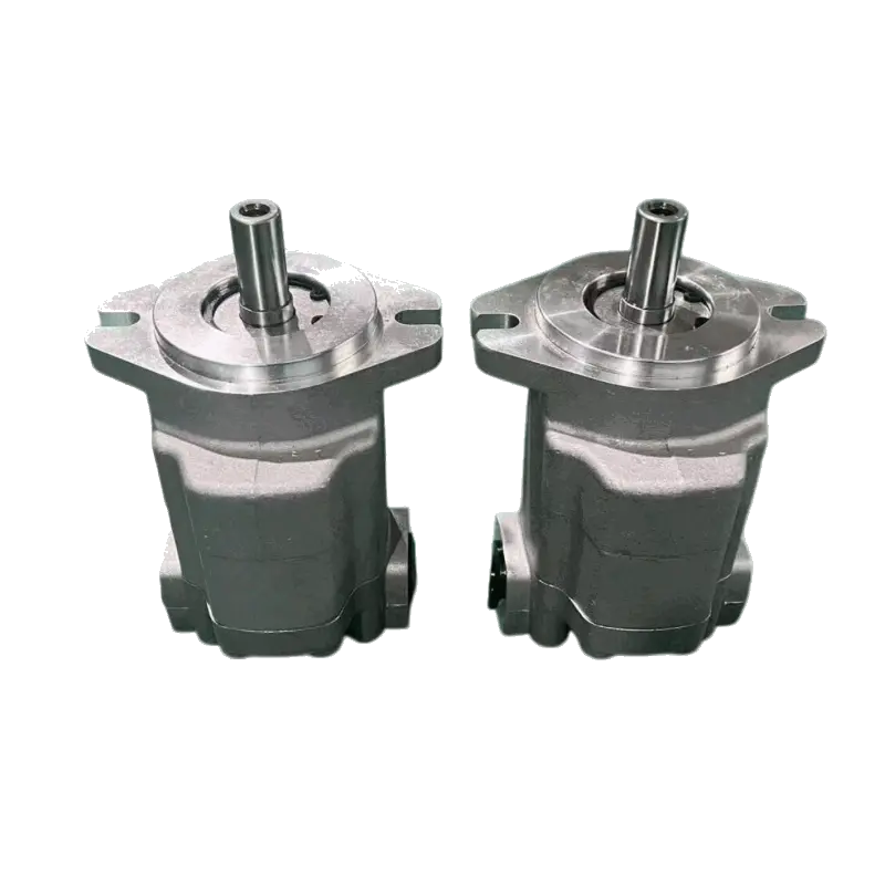
An external gear motor contains two meshing spur gears in a close-fitting housing, one keyed to the output shaft. Fluid entering the inlet acts on the exposed tooth flanks and drives the gears apart, while fluid trapped in the tooth cavities is carried around the housing and expelled at the outlet. Internal gear motors use a smaller external gear meshing inside a larger internal gear and run more smoothly and quietly on the same principle.
The family is simple, rugged, economical, and tolerant of contaminated fluid, which makes it dependable in field equipment, though it runs at moderate pressure, is noisy, and loses efficiency at high speed as leakage grows. Typical duties include conveyor and fan drives, screw conveyors, auxiliary circuits on mobile machinery, and implement drives, which is why Gear Motor Manufacturer ranges remain the default wherever rotation is needed at moderate pressure and continuous speed.
Vane Motors
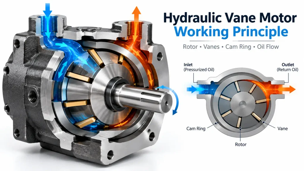
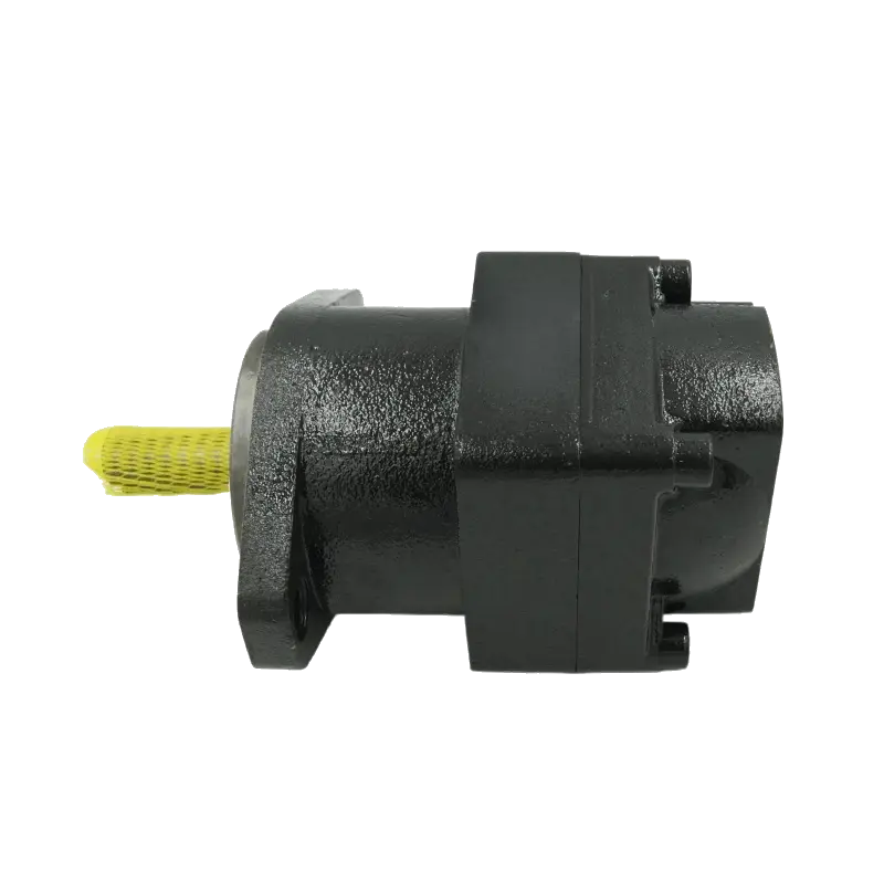
A vane motor generates torque from a pressure imbalance inside a cam ring. A slotted rotor turns within the ring, and vanes held against the ring surface are driven by fluid admitted on one side, turning the rotor toward the low-pressure side. Most designs are hydraulically balanced, so opposing pressure pockets cancel the side load on the shaft and allow continuous running without rapid bearing wear.
That balance gives low flow pulsation, smooth torque, quieter running than gear motors, and quick response to reversal. Vane motors accept lower maximum pressure than piston motors, and because they depend on the vanes sealing against the ring, they are more sensitive to fluid cleanliness and viscosity. Their territory is fixed industrial plant: machine tools, presses, injection molding machines, indexing systems, and industrial fan drives.
Piston Motors
Piston motors form the high-pressure, high-efficiency class. Positive sealing by the pistons lets them tolerate the highest system pressures and return the best overall efficiency in the family, at the cost of higher price, tighter filtration, and greater sensitivity to contamination. They divide according to whether the pistons sit parallel to the output shaft or perpendicular to it.
Axial Piston Motors
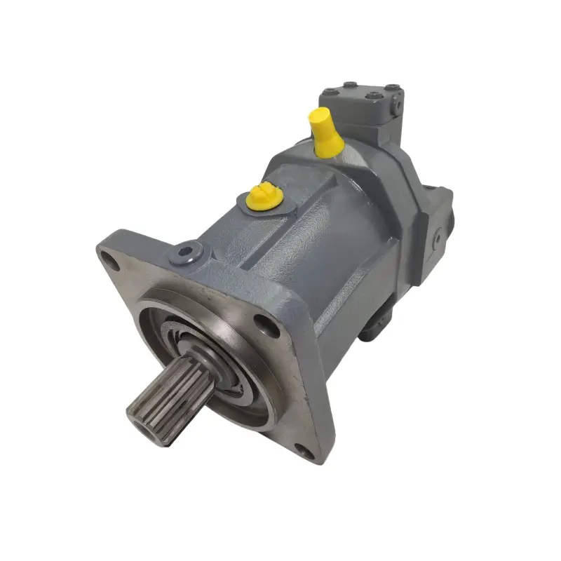
In an axial piston motor, pistons arranged in a barrel parallel to the shaft bear against an inclined plate. Fluid pushes each piston along its bore, and the inclined plate resolves that linear force into rotation. Fixed-displacement versions hold the plate angle constant, while variable versions change it while running, trading torque for speed at constant input flow. That adjustability is why these motors dominate hydrostatic transmissions and serve machine propulsion, travel drives, and winch drives.
Radial Piston Motors
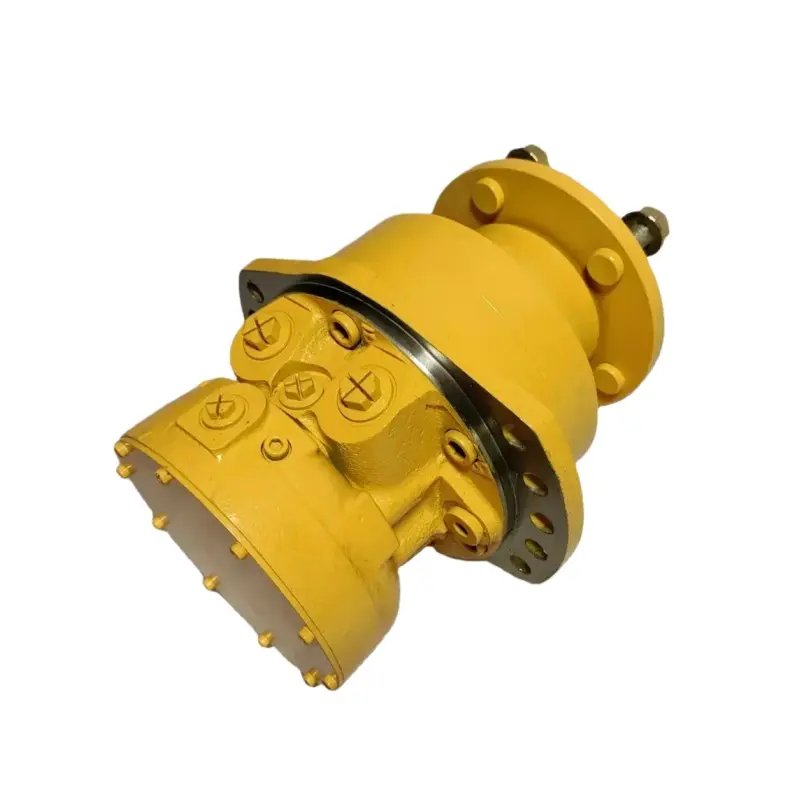
A radial piston motor arranges its pistons perpendicular to the output shaft, radiating from a cylinder block against a surrounding cam ring. Fluid pushes each piston outward, and the reaction against the ring turns the block and shaft. An odd number of pistons keeps at least one producing torque at all times.
The result is very high torque at the shaft without reduction gearing, which removes a maintenance item, shortens the drivetrain, and improves low-speed control by eliminating reducer backlash. Research on fluid efficiency in low-speed high-torque motors shows that viscosity measurably affects usable torque in these conditions. Typical duties include heavy winches, ship cranes, tunnel boring, and mining equipment.
Orbital Motors (Gerotor and Geroler)
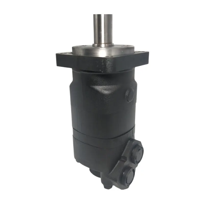
An orbital motor uses a gerotor set, in which an inner rotor with one fewer tooth than the surrounding stator rolls inside it. As the rotor orbits, the spaces between the teeth expand on the inlet side and contract on the outlet side, and a commutator valve distributes fluid to the correct chambers. The geroler variant uses rollers in place of stator teeth, reducing friction and allowing higher pressure on the same principle.
The design yields large torque from a small, light, self-contained package that tolerates contaminated fluid, though maximum speed is lower than a gear or vane motor’s and peak efficiency is good rather than exceptional. That balance is why the family has become the workhorse of mobile low-speed drives, and why an Orbit Motor Manufacturer product can be bolted directly to a wheel hub, an auger, or a conveyor head shaft with no gearbox. Typical duties include harvester and implement drives, augers, loader wheel drives, trenchers, and sweeper brushes.
Comparison of the Four Hydraulic Motor Types
The figures below are typical ranges for each family rather than fixed values, because any product series sits inside a range according to its design priorities and displacement, so confirm actual figures against the data sheet.
| Type | Typical Strength | Typical Displacement | Typical Max Pressure | Typical Speed Range | Typical Efficiency | Contamination Tolerance | Relative Cost | Typical Applications |
| Gear | Simple, economical | 1 to 200 cc/rev | up to 250 bar | 500 to 3000 rpm | 70 to 85 percent | High | Low | Conveyors, fans, auxiliary drives |
| Vane | Smooth, quiet running | 9 to 215 cc/rev | up to 230 bar | 100 to 2500 rpm | 80 to 88 percent | Medium | Low to medium | Machine tools, presses, industrial drives |
| Orbital | High torque at low speed | 8 to 800 cc/rev | 140 to 200 bar | 0 to 2500 rpm | 75 to 90 percent | Medium | Medium | Agricultural machinery, augers, wheel drives |
| Piston, axial | High pressure, high efficiency | a few to 1000 cc/rev | 350 to 450 bar | up to 7500 rpm | 90 to 95 percent | Low | High | Hydrostatic drives, winches, propulsion |
| Piston, radial | Highest torque, very low speed | up to 16000 cc/rev | 350 to 450 bar | 0 to 1000 rpm | 90 to 95 percent | Low | High | Winches, cranes, mining, deck machinery |
Reading the table by speed rather than by name gives the same answer more quickly: gear, vane, and axial piston motors are high-speed, low-torque designs, while orbital and radial piston motors are low-speed, high-torque designs. ISO 4392-1:2002 sets out the standard method for determining the low-speed characteristics of positive displacement motors.
What Are the Applications of Hydraulic Motors?
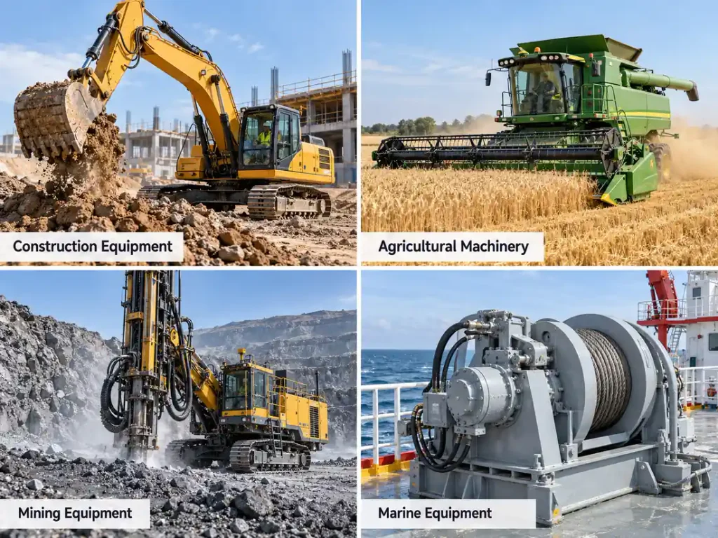
Hydraulic motors are used across five major sectors: construction and heavy equipment, agricultural machinery, material handling and industrial equipment, mining and metallurgy, and marine and offshore equipment. Beyond these, they appear in forestry machinery, municipal vehicles, and specialised industrial machines. The sector determines which family fits, because each imposes its own load profile, duty cycle, contamination exposure, and control requirement.
Mobile equipment driven from an engine or power take-off tends toward contamination-tolerant gear, orbital, and piston designs, while fixed plant tends toward the smooth, repeatable motion of vane and piston motors.
Construction and Heavy Equipment
Excavators use motors for the swing that rotates the upper structure and for track travel, and the two duties differ: swing needs high starting torque, compact size, and controlled acceleration to avoid load sway, while travel needs high pressure and a wide speed range in a closed circuit. Wheel loaders, skid steers, and backhoe loaders use motors for wheel drive, and cranes for winch hoisting. This sector relies on rugged Hydraulic Parts for Construction Industry components that tolerate dust, shock, and rapid load reversal.
Agricultural Machinery
Agricultural work combines dust, moisture, wide temperature swings, and long seasonal duty with field rather than workshop maintenance, which pushes designers toward sealed, contamination-tolerant motors. Combine harvesters use motors for header and reel drives and the unloading auger, and tractors and implements for mowers, balers, tillers, and sprayer pumps. With intermittent and intense duty cycles, high starting torque and infrequent servicing matter more than peak efficiency, so orbital motors are the usual choice.
Material Handling and Industrial Equipment
Industrial plant prizes repeatability, controllability, and low noise rather than force tolerance. Conveyor drives move bulk and packaged material, and several motors may be arranged in series along one line so that a single pump supplies them all. Mixers and agitators turn impellers under changing batch resistance, injection molding machines rotate the screw during plasticising, and presses use motors for clamping and return. Robots, indexing tables, packaging machines, and roll feeds also depend on smooth torque at controlled speed, where vane and variable axial piston motors excel.
Mining and Metallurgy
Mining runs continuously in dust, heat, and vibration, and a stopped machine halts production. Drill rigs use motors for rotary head rotation and for feed, both demanding high pressure and precise speed control. Underground loaders use them for propulsion in confined spaces, shovels for bucket and swing functions, and haulage systems for conveyor drives and winches. Metallurgy adds high ambient temperature and heavy steady loads on roll tables and ladle handling machinery. Radial and high-pressure axial piston motors dominate, because their torque density moves heavy loads without large reduction gearboxes.
Marine and Offshore Equipment
Marine applications add a further constraint: the equipment is often inaccessible for maintenance and the environment is corrosive. Deck winches haul lines and hold loads under tension, and that holding function makes reliability critical. Anchor handling equipment, capstans, davits, and crane slewing drives all use motors, as do steering gear and hatch covers. The governing requirements are high torque at controlled low speed, dependable load holding, and salt corrosion resistance, which makes radial piston motors traditional for winch and anchor duty.
Other Industrial Applications
Outside the five main sectors, motors appear wherever a compact, controllable rotary drive is needed in a demanding environment. Forestry harvesters and mulchers use them for head rotation, feeding, and winching. Municipal vehicles use them for sweeper brush drives, snowplow positioning, snow blower augers, and refuse truck compactors and lifters. Textile machinery, food processing equipment, and industrial fans use them where compactness and speed control outweigh efficiency.
Which Hydraulic Motor Is Best for Each Application?
The table matches common equipment to the motor type usually selected for it. These are typical choices rather than exclusive options, and most applications can be served by more than one family when the circuit is designed accordingly.
| Equipment | Typical Motor Type | Why It Fits |
| Excavator swing drive | Orbital or axial piston | High starting torque and compact body with controlled acceleration |
| Excavator travel drive | Axial piston | High pressure and wide speed range in a closed circuit |
| Skid steer and loader wheel drive | Orbital | Direct wheel mounting with high torque at low speed |
| Crane winch and hoist | Radial piston | Very high torque at low speed with dependable load holding |
| Combine harvester header and auger | Orbital | Contamination tolerance and steady low-speed torque |
| Sprayer and implement drive | Gear or orbital | Economical rotation at moderate pressure in dusty conditions |
| Conveyor drive | Gear or orbital | Low cost at moderate speed, or steady low-speed torque in series |
| Mixer and agitator drive | Orbital or vane | Contamination tolerance, or smooth torque under varying load |
| Industrial fan and blower | Gear or vane | Continuous high speed with low cost or quiet running |
| Injection molding screw drive | Variable axial piston | Variable displacement for combined speed and pressure control |
| Hydraulic press | Vane or radial piston | Smooth controlled squeeze, or high force at low speed |
| Machine tool and rotary table | Vane or axial piston | Low pulsation and precise low-speed positioning |
| Mining drill rotation and feed | Variable axial piston | Continuous duty at high pressure with speed control |
| Tunnel boring and heavy slew | Radial piston | Maximum torque without reduction gearing |
| Deck winch and anchor handling | Radial piston | Extreme torque at low speed with reliable holding |
| Street sweeper and snow blower | Gear or orbital | Compact, economical, and tolerant of cold and contamination |
| Refuse truck compactor and lifter | Orbital or gear | Rugged low-speed torque in a hostile environment |
How to Choose the Right Hydraulic Motor
Choosing a hydraulic motor starts from the load rather than the catalogue. Establish the torque needed to move the load and the speed at which it must move, convert those into a pressure and flow requirement the power unit can supply, then confirm that the family matching the duty also suits the environment, the duty cycle, and the maintenance regime. Pressure and flow requirements the pump cannot meet will invalidate an otherwise suitable choice.
The working principle, torque and speed arithmetic, and installation requirements are treated in the guide to How Does a Hydraulic Motor Work, so this section covers type-level decisions.
Match Torque, Speed and Pressure
Work backward from the load. Determine the torque required to start and sustain motion, remembering that starting torque exceeds running torque for most loads, and check that the motor’s breakaway torque exceeds that figure with margin. Establish the speed range including creep speeds, then calculate the displacement that satisfies the torque requirement at available pressure and confirm the required flow can be supplied. If the arithmetic forces an implausible displacement, the answer is a different family rather than a different size.
Consider Operating Conditions and Duty Cycle
The environment eliminates whole families before the arithmetic begins. Dust, water ingress, and temperature extremes favour the robust sealing of gear and orbital motors, while continuous duty at high pressure favours piston motors, which handle sustained load and heat better than vane designs. Frequent reversal and precise low-speed positioning favour low-pulsation vane and piston motors, and installation space matters on mobile equipment, where the motor must often fit inside a wheel hub.
Compare Fixed and Variable Displacement
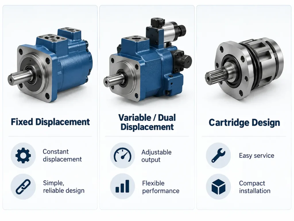
Fixed-displacement motors deliver constant torque per unit of pressure and constant speed per unit of flow, and they are simpler, cheaper, and adequate for most drives with predictable loads. Variable-displacement motors, almost always axial piston designs, change displacement while running, letting one motor trade torque for speed and match a constant-power profile. Variable displacement is justified when a machine must perform efficiently across a wide speed range.
Consider Efficiency, Maintenance and Cost
Overall efficiency determines operating cost over the machine’s life, and it rises from gear through vane and orbital to piston designs; higher efficiency also means less heat and longer seal and fluid life. Contamination tolerance runs the other way, so the more efficient the motor, the stricter the filtration it demands. Balance purchase price against maintenance interval and downtime cost, and where a standard motor cannot be fitted into an existing envelope, a Custom Hydraulic Motor built to the required displacement, mounting pattern, and port configuration is usually less expensive than redesigning the machine.
Frequently Asked Questions
Which hydraulic motor is best for low-speed, high-torque applications?
Orbital and radial piston motors are the two families designed for this duty. Orbital motors are the most compact and economical option and mount directly on a wheel, auger, or shaft without reduction gearing, which suits agricultural and light mobile drives. Radial piston motors deliver much higher torque and smoother rotation at the lowest speeds, suiting heavy winches, cranes, mining equipment, and slew drives. Gear, vane, and axial piston motors are high-speed, low-torque designs.
What is the most common type of hydraulic motor?
By unit volume, gear motors are the most widely used hydraulic motor, because they cost least, are simplest to maintain, and serve many auxiliary duties such as fan and conveyor drives. In mobile low-speed drives specifically, orbital motors are the most common choice, combining high starting torque, compact size, and contamination tolerance at moderate cost. Gear motors dominate the installed population; orbital motors dominate the mobile high-torque segment.
Can one hydraulic pump drive several hydraulic motors?
Yes, and both standard arrangements behave predictably. In a parallel circuit, all motors see the same pressure while pump flow divides between them, so each runs at a speed set by its share of flow, and a flow divider can be fitted where the split must be controlled. In a series circuit, the same flow passes through every motor, so all turn at speeds proportional to that flow while pressure is consumed progressively along the line, meaning the pump must deliver the sum of the individual load pressures.
What is the difference between a hydraulic motor and a hydraulic pump?
A pump converts mechanical input from a prime mover into hydraulic power by moving fluid, while a motor performs the reverse, turning hydraulic power into mechanical rotation. The two share internal geometry, which is why gear, vane, and piston arrangements appear in both, but their priorities differ: a motor must accept flow in either direction, produce useful torque from standstill against a load, and tolerate case pressure. A pump will often rotate when supplied with pressurized fluid, but using it as a motor generally gives lower efficiency and shortened life.