Hydraulic valves sit between the pump and the actuator in almost every fluid power circuit, and they carry the burden of a system’s safety and precision. When a press fails to hold pressure, a cylinder drifts under load, or an excavator boom stalls, the root cause is frequently a valve matched on one specification and overlooked on three others.
Hydraulic valves fall into four functional families that cover every control task in a fluid power circuit: directional control valves decide where fluid travels, pressure control valves decide how much pressure the system may build, flow control valves decide how fast actuators move, and proportional and servo valves combine these functions with continuous, electronically variable adjustment. Within the pressure family, relief, reducing, sequence, counterbalance, and unloading valves each govern a distinct pressure behavior, and directional valves are described by a numbering system stating port count and spool position count.
This guide examines each family, its working principle, and the selection criteria that determine whether a valve performs reliably or becomes a recurring maintenance problem.
What Hydraulic Valves Do in a Hydraulic System
A hydraulic valve regulates the movement of pressurized fluid so that a system’s force, speed, and direction of motion can be commanded rather than merely generated. Valves perform four basic control actions: they start and stop flow, redirect flow between circuits, limit and modulate pressure, and meter flow rate to set actuator speed.
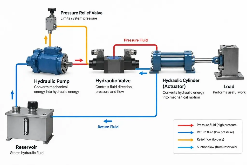
A hydraulic circuit is a chain of energy conversions. The pump converts mechanical shaft power into hydraulic power by moving fluid; valves condition that power into the form the actuator requires; and the cylinder or motor converts it back into mechanical output. The pump is a flow source, not a pressure source in the strict sense, which is why pressure results from resistance to flow.
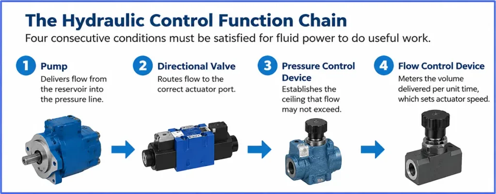
The Control Function Chain
Four consecutive conditions must be satisfied for fluid power to do useful work, and a valve governs each of them.
- A pump delivers flow from the reservoir into the pressure line.
- A directional valve routes that flow to the correct actuator port.
- A pressure control device establishes the ceiling that flow may not exceed.
- A flow control device meters the volume delivered per unit time, which sets actuator speed.
If any link is missing, the system fails to move, moves unpredictably, or damages itself. A circuit with a correctly sized directional valve but no relief device will hold a load perfectly until the moment it ruptures a seal.
The Three Main Types of Hydraulic Valves
The three main types used in nearly every system are directional control valves, pressure control valves, and flow control valves. A fourth family, proportional and servo valves, adds continuous electronic modulation on top of these three functions and is best understood as a control method that spans them rather than a separate control objective.
Catalogues sometimes present long numbered lists of valve varieties, which obscures the fact that classification is functional. A valve is defined by the job it performs in the circuit, not by the shape of its body.
| Functional Family | Control Objective | Typical Members | Command Type |
| Directional control | Fluid path and direction | Spool valves, rotary valves, check valves | Discrete |
| Pressure control | System and branch pressure | Relief, reducing, sequence, counterbalance, unloading valves | Mostly automatic |
| Flow control | Volumetric flow rate | Throttle valves, flow control valves, divider valves | Manual or compensated |
| Proportional and servo | Continuous position, speed, force | Proportional directional and pressure valves, servo valves | Electronic, closed or open loop |
Directional Control Valves
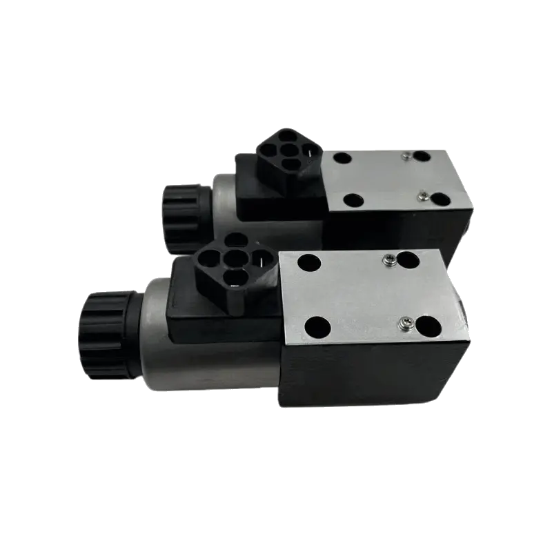
Directional valves, available as Directional Valve Manufacturer options across most industrial and mobile configurations, establish which path fluid follows and therefore which way an actuator moves. A spool slides inside a bored body and its lands open and close passages as it shifts. A three-position spool can extend a cylinder, retract it, or block all ports to hold position, and the blocked condition is what allows a machine to remain stationary without hydraulic power being consumed.
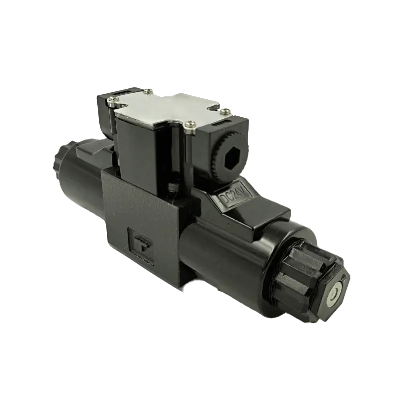
The naming convention states port count first and spool position count second.
| Designation | Meaning | Common Use |
| 2/2 | Two ports, two positions | Simple on and off flow control |
| 3/2 | Three ports, two positions | Single-acting cylinder control |
| 4/2 | Four ports, two positions | Double-acting cylinder, no hold position |
| 4/3 | Four ports, three positions | Double-acting cylinder with a neutral hold condition |
The centre condition matters as much as the port count. A closed-centre spool blocks pressure and tank ports in neutral, which suits systems that must hold a load or run multiple functions from one pump. An open-centre spool connects pump to tank in neutral, which reduces heat generation when no function is demanded.
Pressure Control Valves
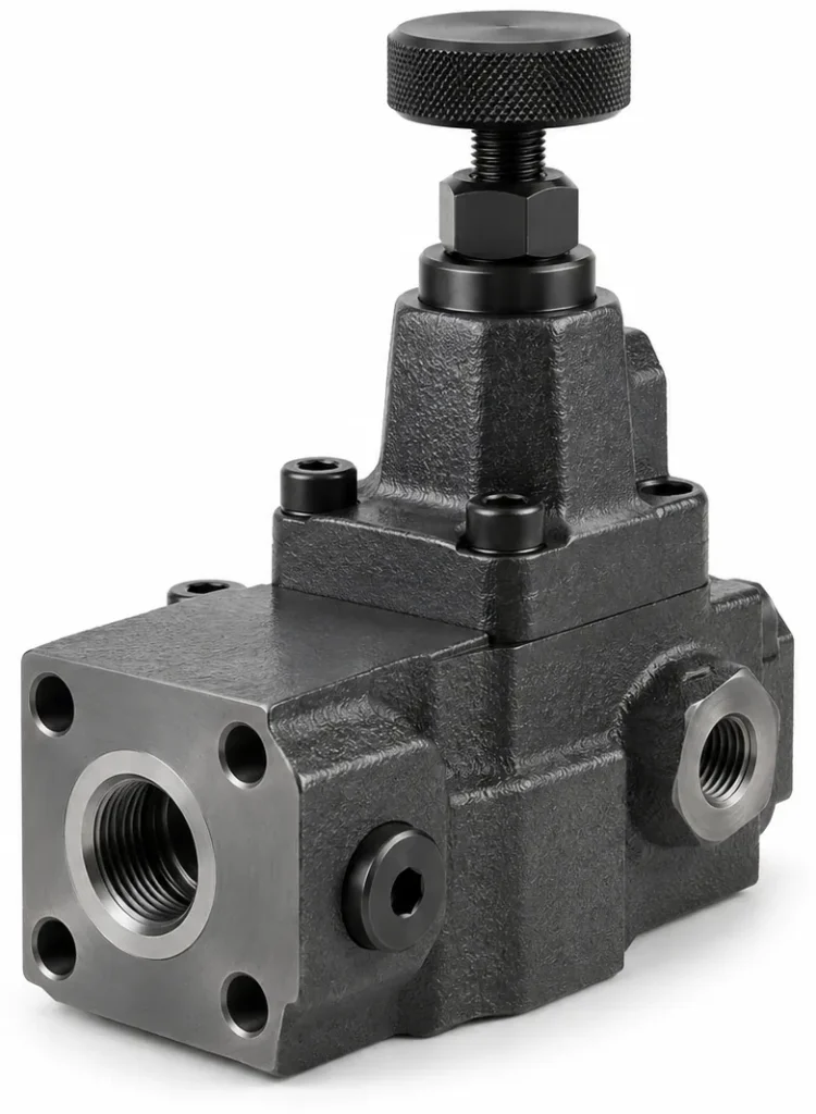
Pressure valves determine how much pressure may exist at a given point in the circuit. The full Hydraulic Valve Manufacturer range covers each of these functions in both direct acting and pilot operated form. Unlike directional valves, which respond to an operator command, most pressure valves act automatically when pressure reaches a preset threshold, and this self-acting behavior is why they form the safety layer of a system.
| Valve Type | Function | Typical Application |
| Pressure relief valve | Limits maximum system pressure by diverting excess flow to tank | Pump protection, overpressure safety |
| Pressure reducing valve | Maintains a constant lower pressure downstream of its setting | Branch circuits feeding sensitive components |
| Sequence valve | Opens at a preset pressure to start a second actuator or circuit | Clamping before machining, multi-cylinder sequencing |
| Counterbalance valve | Maintains back pressure to prevent uncontrolled load descent | Vertical cylinders, lifting equipment, loaded motors |
| Unloading valve | Diverts pump flow to tank when high pressure is not required | Accumulator charging, intermittent high-pressure cycles |
Relief valves divide further by construction, and the choice between the two designs is one of the most consequential in pressure control. Direct acting relief valves open when system pressure acts directly on the element against a spring. They respond quickly and are simple and compact, but the pressure at which they open drifts upward as flow rises, so they suit low-flow circuits. Pilot operated relief valves use a two-stage arrangement in which a small pilot stage controls a larger main stage. The pilot flow is small and nearly constant, so the setting remains stable across a wide flow range, making them the appropriate choice for high-pressure, high-flow systems where stability and low noise matter.
Flow Control Valves
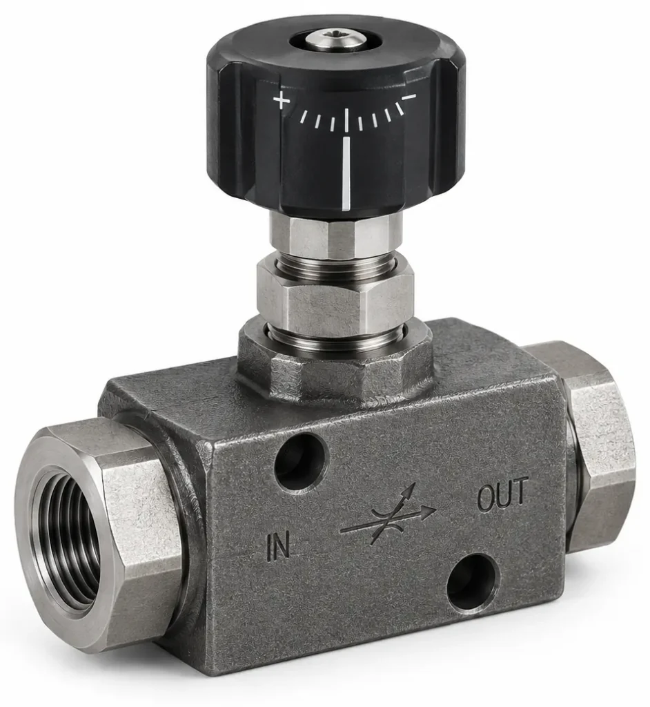
Flow control valves regulate volumetric flow rate, and because actuator speed is proportional to flow, they are the components that set machine motion speed.
Two placement options dominate practical design. Meter-in control restricts flow entering the actuator, which gives stable speed under a resistive load but produces erratic behavior under an overrunning load because the actuator can be driven by the load faster than the meter admits fluid. Meter-out control restricts flow leaving the actuator, which maintains back pressure and gives firm control of an overrunning load, at the cost of higher heat generation.
Pressure compensation is the second major distinction. An uncompensated throttle valve maintains a fixed orifice area, so the pressure drop across it, and therefore the flow through it, varies whenever the load changes. A pressure-compensated flow control valve maintains a constant pressure drop across the metering orifice, so flow remains constant even as load pressure shifts.
Proportional and Servo Valves
Proportional and servo valves convert an electrical command into a continuously variable hydraulic output rather than an on or off state. Instead of selecting one of two or three spool positions, these valves position the spool proportionally, which allows speed, position, and force to be controlled along a continuum.
The two technologies differ in feedback architecture and achievable performance. A proportional valve typically drives the spool with a proportional solenoid and may include spool position feedback; a servo valve usually employs an internal feedback mechanism such as a torque motor acting through a flapper-nozzle pilot to achieve much tighter control.
| Characteristic | Proportional Valve | Servo Valve |
| Command resolution | Continuous, stepped by signal and hysteresis | Continuous, high resolution |
| Typical dynamic response | Moderate, suitable for many motion profiles | High, suitable for demanding closed-loop control |
| Internal feedback | Optional spool feedback | Integral, high-gain |
| Fluid cleanliness sensitivity | Moderate | High |
| Relative cost | Lower | Higher |
A servo valve demands stricter filtration than a proportional valve because its pilot clearances are far smaller, and contamination that a proportional valve tolerates will degrade servo performance or cause it to stick. Where a machine requires moderate accuracy at lower cost, a standard Proportional Valve Manufacturer product line is usually the more practical answer, and where control accuracy governs, the extra filtration and cost of a servo valve are justified.
Valve Configuration, Actuation, and Specifications
Beyond its functional family, a hydraulic valve is defined by how it is actuated, how it is configured, and what its rated specifications are. Actuation describes the mechanism that moves the valve element, configuration describes the port and position arrangement, and specifications describe the pressure, flow, and material limits within which the valve operates.
Valve Actuation Methods
- Mechanical actuation moves the element through a lever, pedal, cam, or roller. It is simple and requires no electrical supply, but it cannot be commanded from a control system.
- Pilot actuation uses a small pressurized flow to move the main element, and because the pilot signal carries little energy it suits hazardous environments where electrical equipment is undesirable.
- Electrical and electronic actuation uses a solenoid to convert a current signal into mechanical motion. Solenoid force is limited, which is why high-flow valves often combine a solenoid pilot with a hydraulic main stage.
- Manual adjustment on pressure and flow valves sets a threshold or orifice size rather than switching the valve, and is typical for valves tuned once during commissioning.
Key Specification Parameters
| Parameter | What It Describes | Selection Note |
| Maximum rated pressure | Highest pressure the valve is designed to withstand | Must exceed system pressure with margin, not merely match it |
| Flow capacity | Volume the valve handles per unit time | Undersizing causes pressure drop and heat; oversizing reduces control sensitivity |
| Pressure drop at rated flow | Energy lost across the valve | Accumulates across valves and reduces available actuator force |
| Cracking or set pressure | Pressure at which a pressure valve begins to open | Must be calibrated to the circuit, not copied from the pump rating |
| Port size and interface | Thread, flange, or manifold fitting | Must match the manifold and cavity standard in the design |
| Body and seal material | Compatibility with fluid and environment | Governs corrosion resistance, temperature range, and seal life |
| Fluid cleanliness tolerance | Contamination level the valve accepts | Drives filtration grade and maintenance interval |
Pressure drop deserves emphasis because it is frequently underestimated. Every valve through which fluid passes removes energy from the circuit, and in a system with several valves in series those losses accumulate into heat, reduced actuator force, and shortened seal life. The safety and design requirements governing this aspect of system layout are set out in ISO 4413, the international standard for hydraulic fluid power systems and their components.
Hydraulic Valve Applications Across Industries
Hydraulic valves are used across at least five major sectors: construction and earthmoving machinery, agricultural machinery, material handling and lifting equipment, industrial manufacturing and metal processing, and mining and metallurgy. Each sector places different demands on the valve set, particularly in terms of duty cycle, load variation, contamination exposure, and control precision.
| Sector | Representative Machines | Dominant Valve Functions | Key Operating Challenge |
| Construction and earthmoving | Excavators, loaders, dozers | Directional control, load holding, pressure limiting | Rapid load change, shock, outdoor contamination |
| Agricultural machinery | Tractors, harvesters, implements | Directional and proportional control, flow control | Wide temperature range, field dust, remote control |
| Material handling and lifting | Forklifts, cranes, aerial platforms | Counterbalance and check functions, directional control | Safety-critical load holding, precise lowering |
| Industrial manufacturing | Presses, machine tools, injection molding | Proportional and servo control, sequence and pressure control | Repeatability, speed, clean fluid, high duty cycle |
| Mining and metallurgy | Drills, crushers, mill equipment | Pressure limiting, flow control, high-pressure directional control | Extreme pressure, heat, heavy contamination |
Two patterns emerge from this distribution. First, load holding appears in every sector where a raised mass could descend under gravity, which is why counterbalance and check functions are treated as safety components rather than convenience features. Second, the more precise a sector’s motion requirement, the more likely it is to rely on proportional or servo control. Construction machinery in particular depends on rugged Hydraulic Parts for Construction Industry components that tolerate dust, shock, and rapid load reversal.
Hydraulic Principles Behind Valve Operation
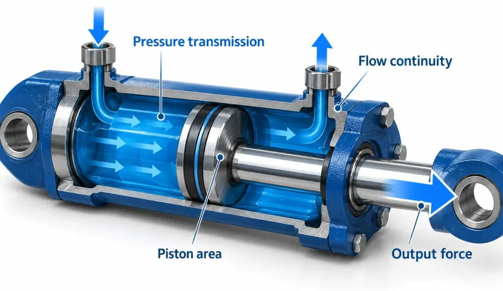
Hydraulic valves operate on a small set of physical principles that apply to every fluid power circuit. Pressure applied to a confined fluid is transmitted undiminished in all directions, pressure equals force divided by area, flow into a closed volume must equal flow out of it, and restricting a flow path converts pressure energy into heat.
The frequently repeated idea that hydraulics rests on seven fixed principles is a simplification rather than a formal standard. The governing relationships originate from a few fundamentals, and understanding those allows a problem to be diagnosed from first principles.
Pressure Transmission and Flow Continuity
The foundational relationship is known as Pascal’s principle: a pressure change applied to a confined incompressible fluid is transmitted undiminished throughout the fluid and to the walls of its container. As described in the standard reference on Hydraulic machinery, this is the mechanism that allows a small force acting on a small piston area to produce a larger force on a larger piston area, because pressure is uniform while force is pressure multiplied by area.
Two further relationships govern valve behavior. Continuity requires that the flow entering a fixed volume equal the flow leaving it, which is why metering flow on either side of an actuator controls its speed. Bernoulli’s relationship holds that where a flow path narrows and velocity rises, pressure falls. A throttle valve exploits this trade deliberately, forcing fluid through a restriction and converting the resulting pressure difference into heat.
Fluid cleanliness is the fourth principle in practice. Clearances in a valve spool are measured in micrometres, and particles comparable to those clearances cause sticking, leakage, and accelerated wear. International standard ISO 4406 expresses fluid contamination as a code reporting particle counts at defined size thresholds, and valve manufacturers specify the code a component requires.
How to Choose the Right Hydraulic Valve
Choosing the right valve requires matching it to the circuit rather than to a catalogue rating. Define the maximum working pressure and required flow first, then select the functional family, then confirm configuration, interface, materials, and control method. A valve that satisfies pressure but not flow, or flow but not response, will cause instability or heat even if every individual specification looks acceptable.
Selection proceeds as a sequence, with each step constraining the next. Starting with pressure and flow prevents choosing a valve family out of habit, and ending with documentation checks prevents ordering a component whose interface does not exist in the machine.
Step-by-Step Selection Checklist
- Establish the maximum working pressure at the valve location, including transient peaks, and select a valve whose rated pressure exceeds it with margin.
- Determine the continuous and peak flow through the valve, then verify the pressure drop at those flows against the actuator force budget.
- Identify the control objective: direction, pressure, flow rate, or continuous modulation.
- Specify the configuration, including port count, position count, and centre condition for directional valves.
- Confirm the mounting interface, port size, and cavity standard match the manifold in the design.
- Match body material, seal material, and fluid cleanliness tolerance to the operating fluid and environment.
- Choose the actuation method based on the control system: manual, pilot, or electrical.
- Confirm the response time and control precision suit the machine’s motion requirement.
- Verify that the valve’s failure behavior is safe, including what happens if the electrical command is lost.
Common Selection Mistakes
Several errors recur often enough to be worth naming. Selecting a valve by pressure rating alone ignores the flow-dependent pressure drop that will reduce available force and generate heat. Ignoring flow-induced instability leads to circuits whose speed changes whenever the load changes. Using a pilot operated valve on a low-flow circuit adds complexity and cost without delivering its stability advantage.
Maintenance and Troubleshooting Basics
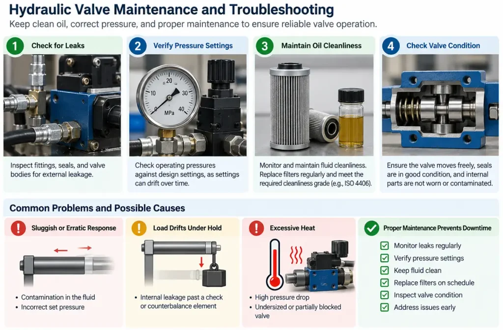
Most hydraulic valve failures originate in the fluid rather than in the valve. Contamination causes spool sticking, erosion, and internal leakage; incorrect set pressure causes either nuisance opening or inadequate protection; and neglected seals lead to external leakage and pressure loss. A maintenance routine focused on fluid condition and pressure setting verification prevents the majority of valve-related downtime.
Practical maintenance addresses four conditions. Leaks should be monitored at fittings, seals, and valve bodies. Operating pressures should be verified against design settings, because settings drift with thermal cycling and spring fatigue, and a relief valve that opens low limits machine capability while one that opens high removes protection. Oil cleanliness should be measured rather than assumed, with filtration maintained at the grade the most sensitive valve requires.
When a valve problem appears, the diagnostic value of the symptoms is high. Sluggish or erratic response usually indicates contamination or incorrect set pressure. A load that drifts under hold suggests internal leakage past a check or counterbalance element. Excessive heat points to pressure drop across an undersized or partially blocked valve.
FAQ
When should a proportional valve be used instead of a servo valve?
A proportional valve is the better choice when the machine requires variable speed or moderate position control at lower cost, simpler electronics, and tolerance for ordinary industrial filtration. A servo valve is warranted when the application demands high control accuracy, fast dynamic response, and closed-loop position or force regulation, and when the system can support the stricter fluid cleanliness regime that servo clearances require.
How does valve pressure drop affect overall system efficiency?
Every valve in the flow path removes energy from the circuit, and that energy appears as heat rather than useful work. In a circuit with several valves in series, the losses accumulate and reduce the pressure available at the actuator, which the machine compensates for by requiring more pump output and generating more heat. Keeping pressure drop low through correctly sized valves improves efficiency, lowers fluid temperature, and extends seal and fluid life.
When does a system need a separate safety relief circuit?
A separate safety relief path is warranted whenever the primary pressure control valve cannot be relied upon to protect the system under all conditions, which includes systems holding suspended loads, circuits with energy accumulation from an overrunning load, and installations where a single blockage or valve failure could produce uncontrolled pressure rise. In these cases, protection is provided by independent means, so that no single failure removes the system’s overpressure defense.