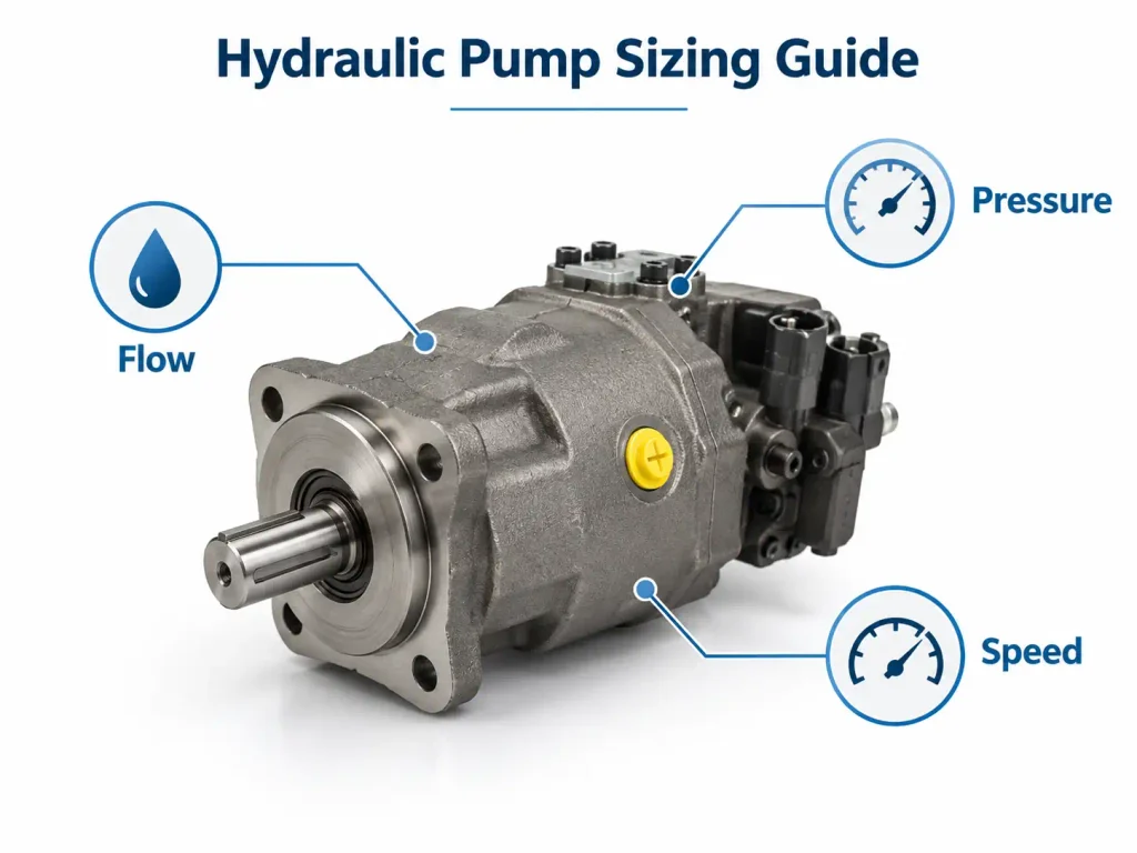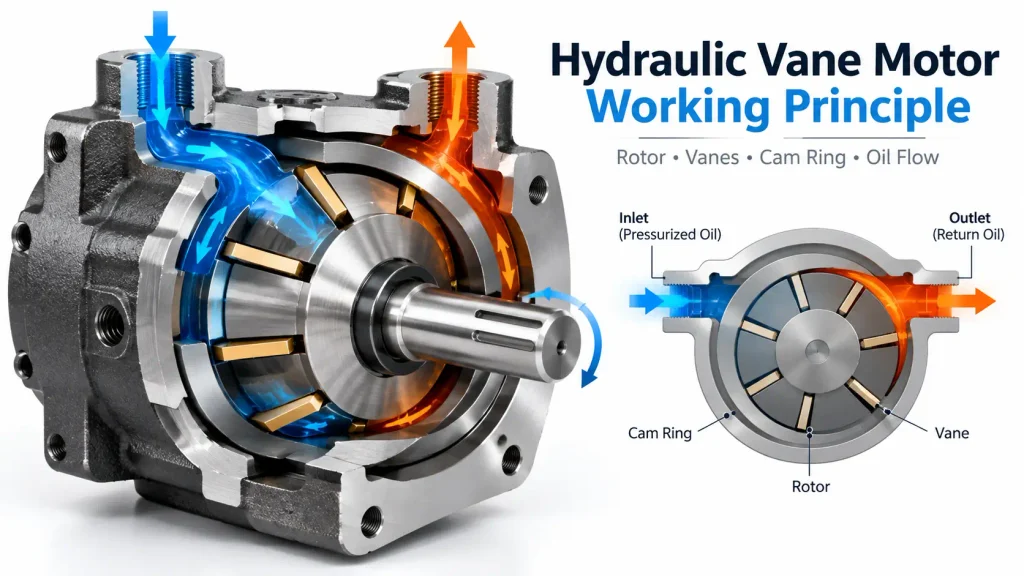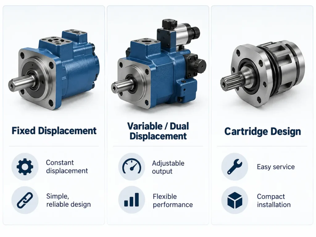
A hydraulic control valve is a device installed between the pump and the actuator that regulates the flow rate, pressure, and direction of hydraulic fluid, translating an operator or controller input into precise mechanical motion. It works by shifting an internal moving element, usually a spool or a poppet, inside a precisely machined bore. As that element moves, it opens, closes, or partially obstructs internal passages, reconnecting the pressure port, tank port, and work ports in different combinations, so pressurized oil is routed to the correct side of a cylinder or motor at the correct rate.
The sections below explain what a hydraulic control valve does, how its internal mechanism produces that control, which types exist, and how to recognize one that is failing.
The Three Functions Every Hydraulic Control Valve Performs
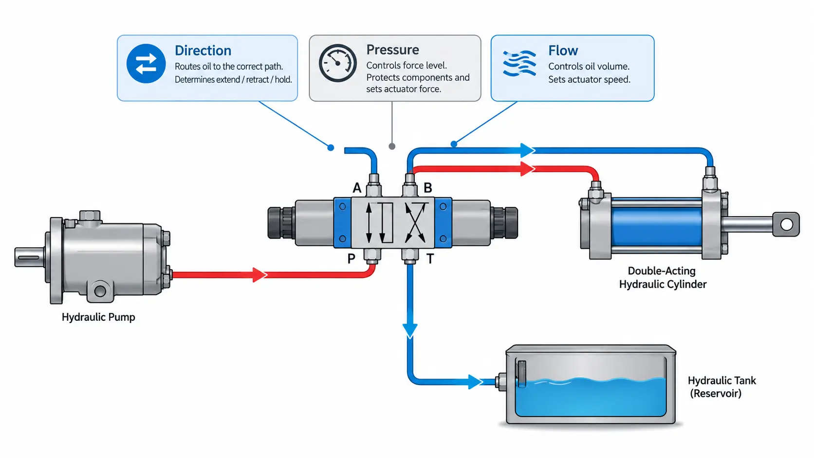
Control valves are grouped by the variable they primarily manage, but real circuits almost always use all three categories together, often stacked in a single manifold or sectioned valve bank.
| Function | What It Controls | Effect on the System | Typical Valve Type |
| Direction | The path oil takes through the circuit | Determines whether an actuator extends, retracts, rotates, or holds position | Directional control valve |
| Pressure | The force level at which oil is delivered | Protects components and sets the force an actuator can produce | Relief, reducing, sequence, counterbalance valve |
| Flow | The volume of oil reaching the actuator | Sets actuator speed independently of load | Throttle, needle, pressure-compensated flow valve |
Directional control is the most visible function to an operator, because it corresponds directly to lever movement. Pressure control is the protective function, and flow control is the speed-setting function. A circuit with direction and pressure control but no flow control will move loads, but at whatever speed the pump and load happen to produce, which is rarely acceptable on a machine that must place a load gently or synchronize two cylinders.
Core Components Inside a Hydraulic Control Valve
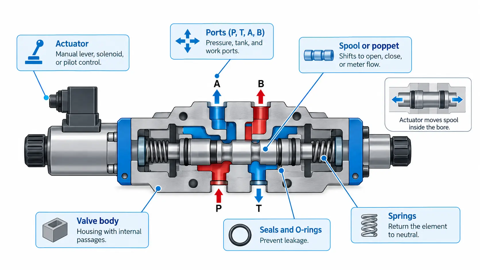
| Component | Function |
| Valve body | Cast iron or machined steel housing containing the internal passages and port connections |
| Spool or poppet | The moving element that opens, closes, or meters flow paths |
| Ports (P, T, A, B) | Entry and exit points for the pressure line, tank return line, and the two work lines to the actuator |
| Springs | Return the moving element to its neutral position when actuation force is removed |
| Seals and O-rings | Prevent internal and external leakage and maintain pressure integrity |
| Actuator | Manual lever, solenoid coil, or pilot piston that displaces the moving element |
The body is engineered to withstand sustained system pressure, and its internal passages are drilled or cast so each port opens into a specific zone of the spool bore. It is worth noting that hydraulic valve manufacturers treat bore geometry and spool clearance as the two most critical tolerances in the component, because they determine both leakage and response.
How Does a Hydraulic Control Valve Work?
A hydraulic control valve works by displacing a moving element inside a close-tolerance bore so that raised sections of that element, called lands, either block or uncover internal passages. When a land covers a passage, flow stops. When a groove between two lands aligns with a passage, flow is admitted. By positioning the element precisely, the valve reconnects its ports in a chosen combination, sending pump pressure to one work port while connecting the other work port to the tank.
This behaviour follows from a principle of fluid power that describes how pressure applied to a confined liquid is transmitted undiminished throughout the system, the same physical basis that allows a small pump to move a very large load in hydraulic machinery. The valve does not create pressure; it decides where existing pressure is allowed to act. Because the moving element has no seal lip of its own, sealing comes from the extremely tight radial clearance between the element and the bore. That is why every spool-type valve has a small, measurable internal leakage by design, and why fluid cleanliness matters so much: a particle large enough to lodge between the element and the bore can score surfaces or jam the element outright.
Spool Versus Poppet Mechanisms
- Spool mechanism. A cylindrical element machined with alternating raised lands and recessed grooves slides axially inside a matching bore. Because the element can stop at any intermediate position, flow can be metered continuously rather than simply switched on or off. The trade-off is a small amount of internal leakage across the lands.
- Poppet mechanism. A conical or ball-shaped element seats against a matching seat to block flow completely. Leakage is very low when closed and the response is fast, but the design suits on/off or limited proportional action rather than fine continuous metering.
| Characteristic | Spool | Poppet |
| Sealing principle | Tight radial clearance between lands and bore | Contact against a seat |
| Internal leakage | Small but always present | Very low when fully seated |
| Flow metering | Continuous, any intermediate position | Primarily on/off |
| Response speed | Fast, proportional to spool travel | Very fast, near-instant switching |
| Typical use | Directional, proportional, and servo control | Check functions, load holding, safety shutoff |
In practice, many circuits combine both. A directional control valve is generally a spool design, while the check and load-holding functions alongside it are almost always poppet-based. As the wider category of control valves is defined, these devices act as the final control element in a system, the last component that acts on the process before the fluid reaches the actuator.
How the Valve Meters Flow and Direction
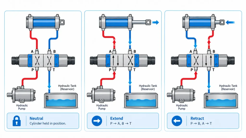
The clearest way to understand directional control is to follow a four-port, three-position valve, written as a 4/3 valve, operating a double-acting cylinder. Its ports are pressure (P), tank (T), and two work ports (A and B). What happens in its centre position depends on the spool’s centre configuration, which is fixed at manufacture.
- Closed centre. All ports are blocked, so system pressure rises to the relief setting and both work ports are sealed, locking the actuator in place.
- Open centre. All ports interconnect, so pump flow passes to tank at minimal pressure while the actuator ports connect to tank and the load may drift.
- Tandem centre. Pump flow returns to tank while the work ports remain blocked, combining pump unloading with a locked actuator.
- Float centre. The actuator ports connect to tank so the cylinder or motor can move freely under external load.
When the spool shifts to one side, it connects P to one work port and the opposite work port to T. Pressurized oil enters one end of the cylinder while oil from the other end returns to the tank, producing extension; shifting the spool the other way reverses those connections and retracts the cylinder. This reversal is the entire basis of directional control, and directional control valves are named for precisely this ability. Valve size is expressed the same way for every spool design, as the number of ways followed by the number of positions. A 2/2 valve works as a simple on/off switch, a 3/2 valve suits a single-acting cylinder, and a 4/3 valve is standard for double-acting cylinders and reversible motors.
Actuation Methods: Manual, Solenoid, and Pilot-Operated
How the spool is displaced determines how precise, how fast, and how automatic the control can be.
| Actuation Method | How It Works | Response and Automation | Typical Applications |
| Manual | A lever, pedal, or handwheel pushes the spool directly | Immediate operator feedback, no automation | Agricultural implements, workshop presses |
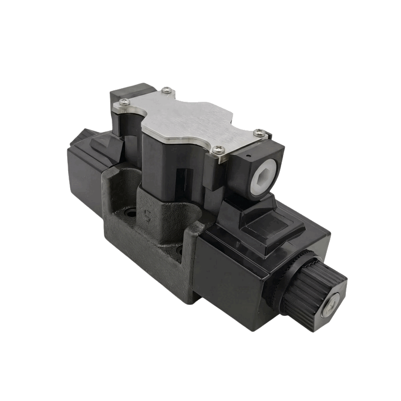
| Solenoid | An electromagnetic coil shifts the spool when energized | Remote and automated control, fast response | Industrial machinery, joystick-controlled equipment |
| Pilot-operated | A small pilot valve controls pressure that moves a larger main spool | Fine control with minimal input force at high pressure | Heavy machinery, injection molding, high-flow circuits |
Solenoid actuation dominates modern equipment because it allows a single controller to manage several functions at once and makes automated sequences possible. Pilot operation is used where the force required to move a large spool directly would be impractical, since the pilot stage amplifies a small input into enough force to shift the main element against spring and flow forces.
The Main Types of Hydraulic Control Valves
Hydraulic control valves fall into four functional families: directional control valves that determine where oil goes, pressure control valves that set and limit force, flow control valves that set speed, and proportional or servo valves that provide continuously variable control rather than fixed positions.
Directional Control Valves
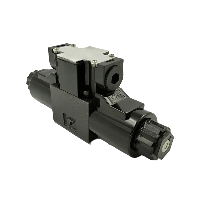
Directional control valves route oil to the correct actuator and provide the return path. Configurations are described by their ways and positions, and common examples include simple on/off valves for single-acting cylinders, three-way valves that alternately pressurize two circuits, and four-way valves that serve double-acting cylinders and reversible motors. Check valves belong to this family as single-direction devices that prevent backflow and hold pressure on one side of a circuit.
Pressure Control Valves
Pressure control valves manage force and protect components, and their main types behave quite differently:
- Relief valves limit maximum system pressure by diverting excess flow to the reservoir once a set threshold is reached, protecting pumps, hoses, and seals.
- Pressure-reducing valves lower the pressure supplied to a secondary circuit that requires less force than the main system.
- Sequence valves ensure one actuator completes its stroke before another begins, opening only after a set pressure signals the first movement is finished.
- Counterbalance valves maintain back pressure on a return line so a suspended load cannot fall freely if a hose fails or the directional valve shifts abruptly.
- Unloading valves divert excess flow to the reservoir at low pressure when demand drops.
Load-holding and sequencing are especially critical on lifting equipment, where construction machinery hydraulic parts must keep a raised boom under control regardless of what the operator does next.
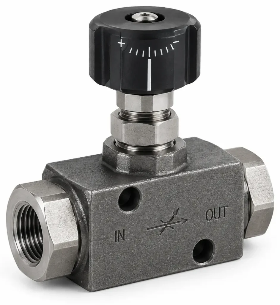
Flow Control Valves
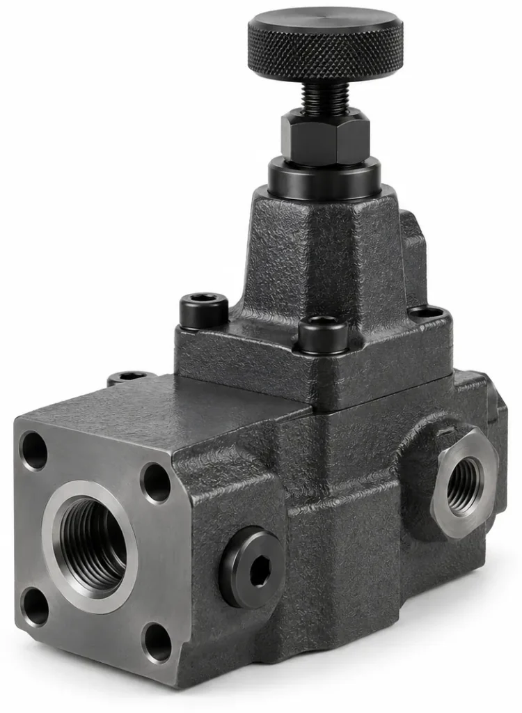
Flow control valves determine actuator speed, because the speed of a cylinder or motor is a function of flow rate rather than pressure. They work by limiting the cross-sectional area available to the fluid.
- Throttle valves use a small fixed or adjustable orifice to restrict flow, slowing actuator movement.
- Needle valves use a tapered needle to allow gradual, fine adjustment of the passage area, useful at low flow rates.
- Pressure-compensated flow control valves adjust their opening automatically to hold a constant flow rate even as load pressure changes.
Where speed must be held constant against a varying load, pressure compensation is essential. Where speed simply needs trimming, a basic throttle or needle design such as a throttle and one-way flow control valve is sufficient.
Proportional and Servo Valves
Proportional valves accept an electrical input signal and shift the spool continuously in proportion to that signal, so the actuator accelerates and decelerates smoothly instead of stepping between fixed positions. Servo valves go further by using closed-loop feedback, comparing actual actuator position against the commanded value and correcting in real time. These designs deliver the highest precision available in fluid power, and they cost accordingly, requiring tighter tolerances and much cleaner fluid than standard directional or pressure valves. Where positioning errors are unacceptable, as in precision industrial automation, a servo valve is often the only design that meets the requirement.
How Does a Hydraulic Control System Work?
A hydraulic control system works by converting mechanical energy into hydraulic energy at a pump, transporting that energy as pressurized fluid, controlling and distributing it through a bank of valves, converting it back into mechanical work at a cylinder or motor, and returning the fluid to a reservoir where it is filtered, cooled, and pumped again. The control valve is the stage where the system decides how much of the pump’s output reaches each actuator and in what form.
A typical mobile machine circuit is more layered than a single valve suggests. A relief valve sits close to the pump outlet to cap system pressure. A directional valve bank, often with several sections, distributes flow to different actuators. Flow control valves on individual circuits set their speeds, and counterbalance valves protect any actuator holding an unsupported load. This arrangement lets one pump drive several functions simultaneously and safely, which is how an excavator can swing its boom, curl its bucket, and extend an outrigger from a single power source. Whether the application is a harvester attachment or a hydraulic circuit for agricultural equipment running over rough ground, the valve decides whether the machine feels precise or unpredictable.
Open-Center Versus Closed-Center Circuits
The two fundamental circuit architectures behave differently at the valve’s neutral position, with real consequences for pressure, heat, and efficiency.
| Characteristic | Open-Center Circuit | Closed-Center Circuit |
| Neutral position | Pump flow passes to tank through the valve | Pump flow is blocked at the valve |
| Pump behaviour | Fixed displacement, continuously supplying flow | Variable displacement, reduces flow when idle |
| System pressure at idle | Low, since flow returns to tank | Held at full pressure, ready at the valve |
| Energy efficiency | Lower when nothing is moving | Higher when functions are idle |
| Typical use | Simple circuits with a fixed pump | Machines with load-sensing pumps |
This explains why two machines with similar lifting capacity can differ markedly in fuel consumption and oil temperature. An open-centre circuit keeps circulating oil to tank while idle, wasting energy as heat, while a closed-centre circuit delivers pressure on demand and is more efficient but requires a pump that can vary its displacement. The fluid path from pump to actuator and back in both arrangements is described in the wider treatment of hydraulic circuits.
Where Hydraulic Control Valves Are Used
Hydraulic control valves are used wherever fluid power must be directed, throttled, or protected. The industries that rely on them most heavily combine high force, precise motion, and continuous duty cycles, including construction and mining machinery, agricultural equipment, industrial production machinery, and marine and aerospace systems.
| Industry | Control Requirement | Typical Valve Emphasis |
| Construction and mining | High force with simultaneous multi-function operation | Multi-section directional valve banks, counterbalance and relief protection |
| Agriculture | Stable speed and reliable lifting over variable terrain | Flow control, load sensing, robust actuation |
| Industrial machinery | Repeatable cycles and precise positioning | Proportional and servo valves, pressure-compensated flow control |
| Marine and aerospace | Reliability under extreme pressure and temperature | High-integrity directional and pressure control, minimal leakage |
Industrial applications such as presses and injection molding machines depend on consistent valve behaviour to keep cycle times repeatable. Mobile equipment demands durability and tolerance of dirty, hot, and vibrating conditions, while marine and aerospace applications place the emphasis on reliability, because a valve that fails at the wrong moment is a safety event rather than a maintenance inconvenience.
FAQ
What is the difference between a hydraulic control valve and a hydraulic pump?
A pump converts mechanical energy into hydraulic energy and produces flow; it has no ability to decide where that flow goes or how much of it an individual actuator receives. A control valve consumes no energy itself and produces no flow. It manages the flow the pump creates, directing it, limiting its pressure, and restricting its rate. A circuit needs both, because a pump without a valve produces uncontrolled motion and a valve without a pump has nothing to control.
Can a hydraulic control valve be repaired instead of replaced?
Many valves can be rebuilt rather than replaced, particularly when a fault is identified before severe internal damage occurs. The process involves stripping the valve, cleaning all components, assessing wear against the manufacturer’s tolerances, and restoring clearances by replacing worn spools, springs, and seals. Rebuilding is often more economical for large, specialized, or obsolete valves. The determining factor is the condition of the bore and the moving element; if bore surfaces are scored beyond specification, replacement becomes the correct choice.
What fluid cleanliness level do hydraulic valves require?
Required cleanliness depends on valve design rather than on the system as a whole. Standard directional and pressure valves tolerate moderate contamination because their clearances are comparatively forgiving. Flow control valves with small orifices, and especially proportional and servo valves, require substantially cleaner fluid because particles that pass harmlessly through a simple spool can block a metering orifice or jam a closely fitted servo spool. The appropriate target should always be taken from the valve manufacturer’s documentation rather than applied uniformly across a machine.