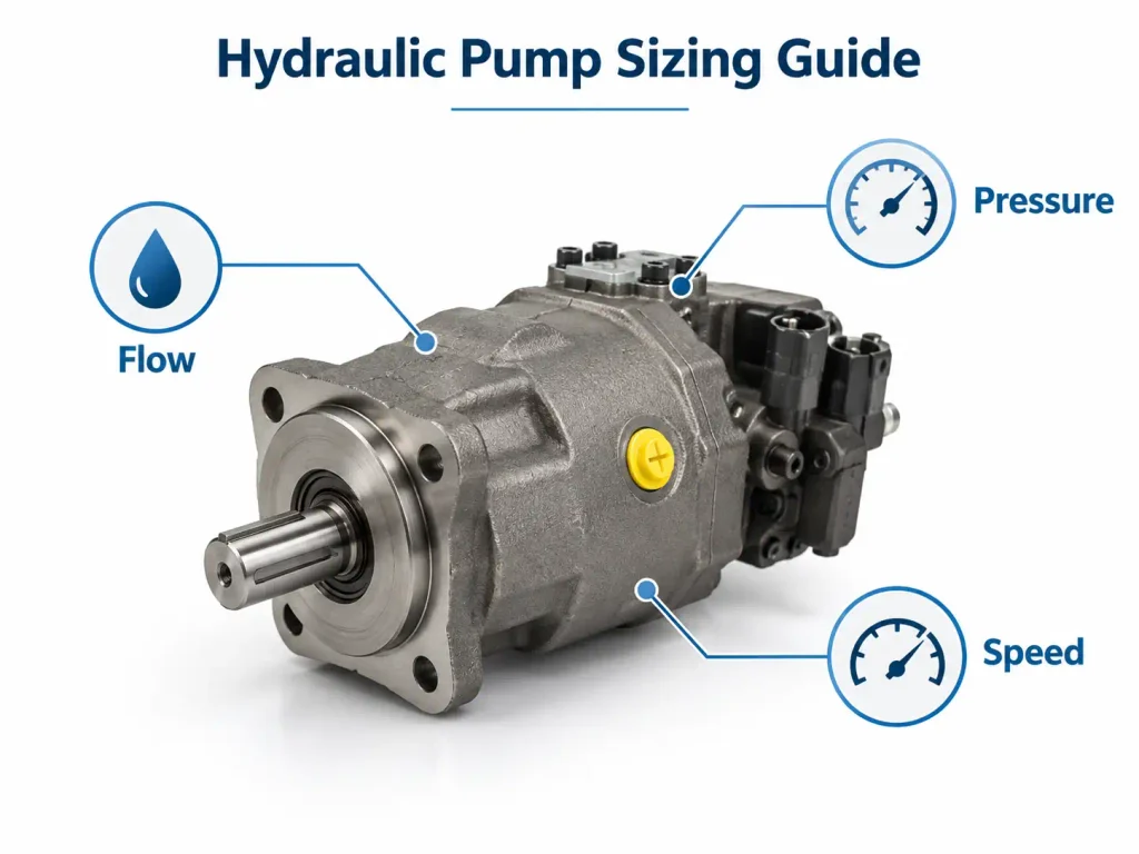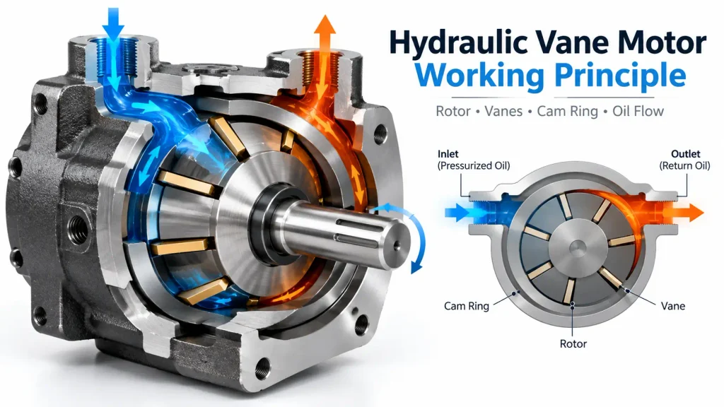
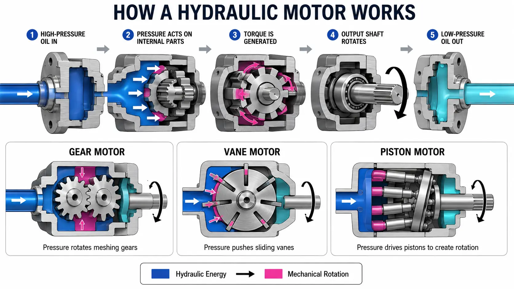
A hydraulic motor works by directing pressurized fluid into internal chambers, where the pressure difference acts on gears, vanes, or pistons. This force rotates an internal assembly connected to an output shaft, converting hydraulic energy into mechanical torque and continuous rotary motion.
What Is a Hydraulic Motor?
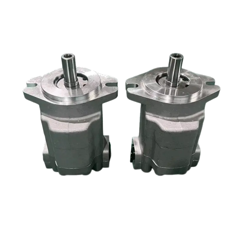
A hydraulic motor is a rotary actuator that converts the pressure and flow of hydraulic fluid into shaft torque and rotational speed.
Its function is broadly opposite to that of a hydraulic pump. A pump receives mechanical power from an electric motor, engine, or other prime mover and converts it into hydraulic flow. A hydraulic motor receives that flow and converts the available hydraulic power back into mechanical rotation.
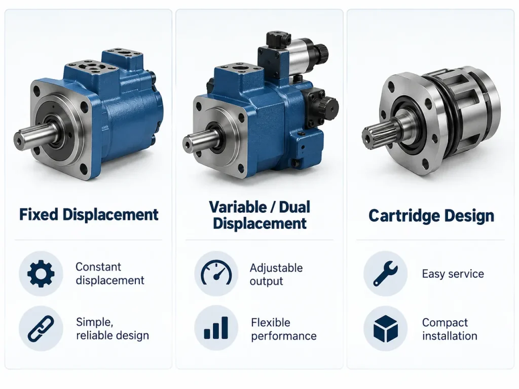
Most motors are either fixed-displacement or variable-displacement designs. A fixed-displacement motor moves a set volume of fluid during every shaft revolution. Its speed is mainly adjusted by changing the inlet flow. A variable-displacement motor can change the amount of fluid required per revolution, allowing a wider torque-speed control range.
How Does a Hydraulic Motor Convert Fluid Power Into Rotation?
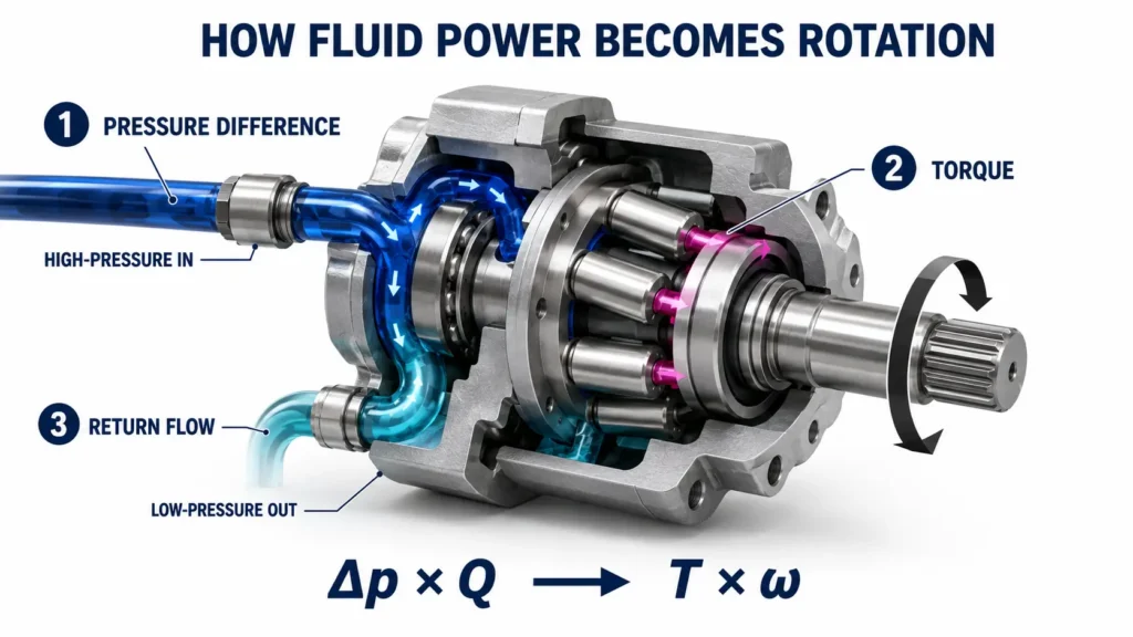
A hydraulic motor creates rotation by maintaining a pressure difference across internal moving surfaces, producing an unbalanced force that turns the rotor and output shaft.
Although the internal mechanism varies by motor type, every design needs a pressure-activated surface, correctly timed inlet and outlet passages, and a mechanical connection to the shaft. A fluid power engineering reference describes the ideal energy relationship as hydraulic pressure multiplied by flow being converted into shaft torque multiplied by rotational velocity.
Pressurized Fluid Enters the Working Chambers
The operating cycle begins when a pump sends fluid to the motor inlet. A valve opens a path into selected working chambers while connecting other chambers to the return line.
The load resists shaft rotation, causing pressure to rise at the inlet. Because the outlet is at a lower pressure, a pressure differential develops across the gears, vanes, or pistons. This differential, rather than inlet pressure alone, produces the useful turning force.
Internal Components Generate Torque
Pressure acts on the internal working surfaces and creates a tangential force. Gears are pushed around their housing, vanes move against a cam ring, or pistons react against a swash plate, bent axis, or cam surface.
The rotating assembly transfers this force to the output shaft. As long as sufficient flow and pressure differential remain available, the cycle repeats and produces continuous torque.
Fluid Leaves Through the Outlet Port
After performing work, the fluid moves into decreasing-volume chambers and exits through the outlet. It then returns to the reservoir through the system’s return line.
Reversing the flow through a suitable circuit usually reverses the motor’s direction. Some fluid also passes through internal clearances without producing work. This internal leakage is necessary for lubrication in many designs, but excessive leakage lowers volumetric efficiency and reduces actual speed under load.
How Do You Power and Control a Hydraulic Motor?
A hydraulic motor is powered by a pump-driven circuit that supplies fluid flow, develops pressure against the load, and uses valves or pump controls to manage speed, direction, and torque.
The pump itself must be driven by a prime mover, such as an engine or electric motor. A basic circuit includes:
- A reservoir that stores and conditions the fluid
- A prime mover that drives the pump
- A pump that produces hydraulic flow
- A relief valve that limits maximum system pressure
- Directional and flow-control devices
- A hydraulic motor connected to the mechanical load
- Return lines, filters, and cooling equipment as required
Flow rate primarily controls motor speed. Pressure rises only as needed to overcome the load, friction, and circuit losses, up to the system’s pressure limit. A directional valve can start, stop, or reverse rotation by changing the fluid path.
Load-holding, braking, or overrunning applications may require additional valves. A motor driving a descending load, for example, can be forced by the load to rotate faster than the supplied flow. Proper circuit design is therefore essential for controlling motion and preventing cavitation or uncontrolled movement.
How Do Pressure, Flow, and Displacement Affect Motor Performance?
Pressure differential primarily determines torque, flow primarily determines speed, and motor displacement establishes the relationship between the two.
These relationships are central to hydraulic motor sizing and troubleshooting. Industry fluid power training guidance likewise emphasizes that pressure, flow, displacement, torque, and speed interact through practical tradeoffs.
| Variable | Primary Effect | Practical Meaning |
|---|---|---|
| Pressure differential | Torque | More differential pressure permits more turning force within rated limits |
| Flow rate | Speed | More usable inlet flow generally increases shaft speed |
| Displacement | Torque-speed ratio | Larger displacement favors torque; smaller displacement favors speed |
| Volumetric efficiency | Actual speed | Internal leakage reduces the flow available for rotation |
| Mechanical efficiency | Actual torque | Friction reduces the torque delivered at the shaft |
Pressure Differential and Output Torque
Motor torque depends on displacement and the difference between inlet and outlet pressure. High return-line back pressure reduces this difference and therefore reduces available output torque.
Starting a stationary load may require more torque than keeping it moving. A motor must consequently be selected for breakaway and starting conditions, not only for normal running torque.
Flow Rate and Motor Speed
For a fixed-displacement motor, shaft speed increases as usable flow increases. Internal leakage means actual speed will be lower than the ideal calculated value, especially when components are worn or fluid viscosity is unsuitable.
A motor should not be operated continuously at a catalog maximum intended only for intermittent use. Continuous speed, inlet conditions, outlet pressure, temperature, lubrication, and duty cycle must all remain within the applicable specifications.
Displacement and Efficiency
At the same pressure differential, a larger-displacement motor can produce more theoretical torque. At the same flow, however, it rotates more slowly. A smaller-displacement motor produces less torque per unit of pressure but turns faster at the same flow.
Actual selection must also consider mechanical and volumetric efficiency, starting load, shock loading, shaft loads, cooling capacity, and expected service life.
What Are the Four Common Types of Hydraulic Motors?
Hydraulic motors can be usefully divided into gear, vane, axial-piston, and radial-piston types, although some classifications combine the two piston designs into one family.
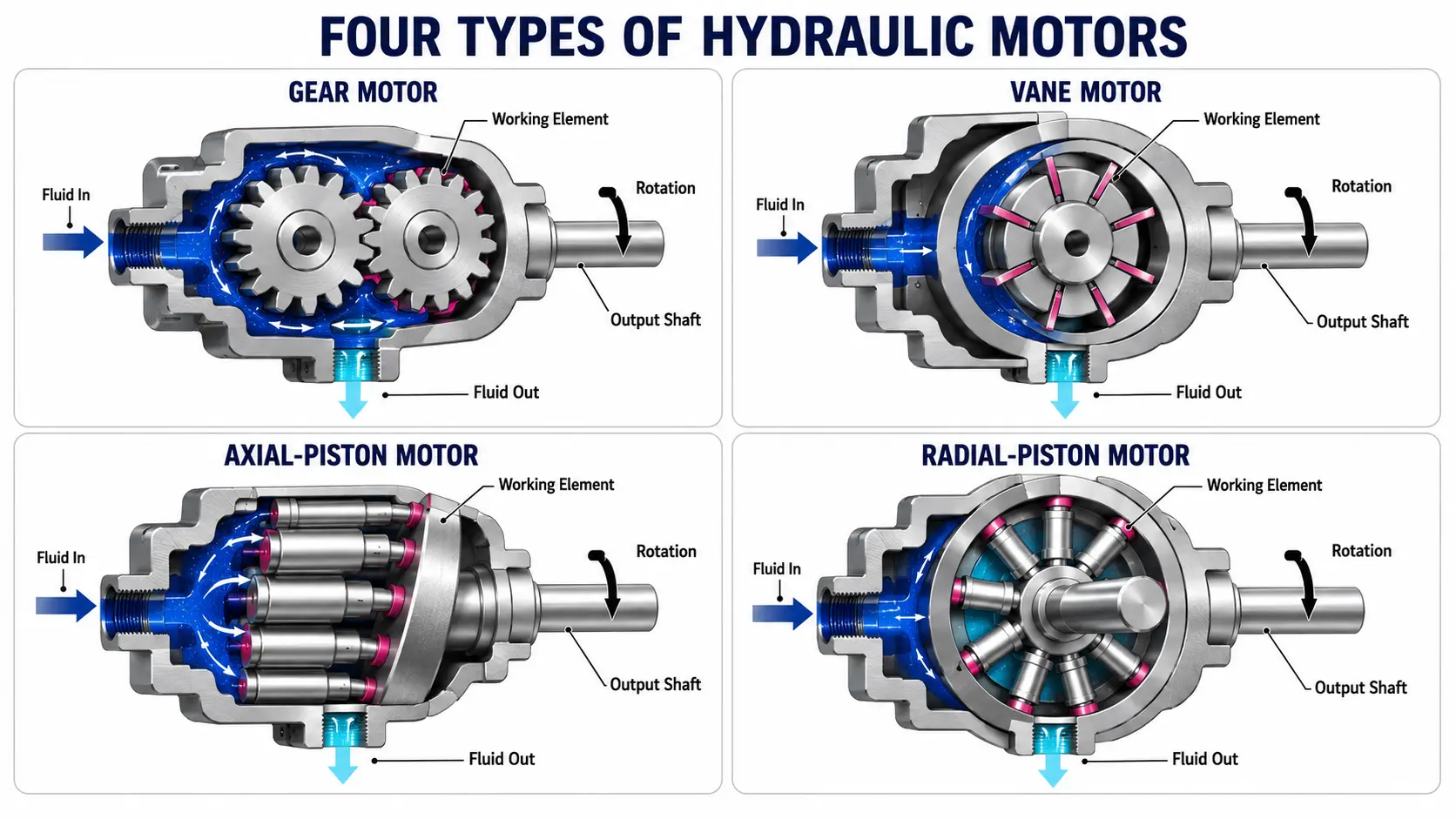
Gerotor and orbital motors are generally treated as internal-gear designs rather than a separate fifth category. Each motor type converts fluid energy through a different internal geometry, producing distinct torque, speed, efficiency, and cost characteristics.
| Motor Type | Internal Mechanism | General Performance Tendency | Main Advantages | Main Limitations |
| Gear | Meshing external or internal gears | Moderate to high speed, moderate torque | Simple, compact, economical, durable | More speed and torque ripple; leakage increases with wear |
| Vane | Sliding vanes in a rotor and cam ring | Smooth medium-speed operation | Relatively quiet, balanced, good efficiency | Sensitive to contamination and unsuitable fluid |
| Axial piston | Pistons arranged along the shaft axis | High pressure, high efficiency, broad speed range | Strong performance and variable-displacement options | Greater complexity and precision requirements |
| Radial piston | Pistons arranged around the shaft | Very high torque at low speed | Excellent low-speed control and starting torque | Larger size and limited high-speed capability |
Gear Motors
An external-gear motor contains two meshing gears inside a close-fitting housing. Pressurized fluid travels around the outside of the gears, creating a force that rotates them. One gear is connected to the output shaft.
Internal-gear motors use an inner and outer gear set. Gerotor or orbital arrangements create expanding and contracting fluid chambers as the gears move eccentrically. Gear motors are valued where simplicity, compactness, and durability are more important than exceptionally smooth low-speed operation.
Vane Motors
A vane motor uses a slotted rotor containing sliding vanes. Pressure acts on the exposed vane surfaces within an eccentric or specially shaped cam ring, generating torque.
Multiple vanes can contribute to rotation at the same time, providing smoother output than many basic gear designs. Correct viscosity, clean fluid, and adequate lubrication are especially important because vane tips and internal surfaces depend on controlled clearances.
Axial-Piston Motors
Axial-piston designs position their pistons generally parallel to the shaft. Pressure drives the pistons against an angled swash plate or bent-axis arrangement, creating rotation.
These motors can operate efficiently at high pressure and are available in fixed- or variable-displacement versions. They are commonly considered where a wide operating range, precise control, or high power density justifies greater mechanical complexity.
Radial-Piston Motors
Radial-piston motors arrange pistons around the shaft. Pressurized fluid pushes the pistons outward against a cam or reaction surface, and the resulting forces rotate the cylinder block or shaft.
Their geometry supports high torque at low speed, often without a separate reduction gearbox. They are suitable for heavy rotary loads but are generally less appropriate for very high shaft speeds.
Why Do Hydraulic Motors Fail?
Hydraulic motors commonly fail because of contaminated or unsuitable fluid, excessive heat, cavitation, aeration, overloading, restricted drainage, poor installation, or mechanical misalignment.
The damaged motor may be only the final victim of a larger system problem. Replacing it without identifying the root cause can lead to another failure.
Contamination and Incorrect Fluid Condition
Particles can score working surfaces, block small passages, accelerate bearing wear, and damage seals. Water can reduce lubricity, promote corrosion, and change fluid behavior. Incorrect viscosity can also create trouble: fluid that is too thin increases leakage, while fluid that is too thick can restrict flow and delay lubrication during startup.
Cavitation, Aeration, and Excessive Heat
Cavitation occurs when local pressure falls low enough for vapor cavities to form and then collapse. Aeration occurs when air enters or remains suspended in the fluid. Both can produce noise, unstable movement, reduced lubrication, and surface damage.
Excessive heat accelerates fluid degradation, hardens or damages seals, reduces viscosity, and increases internal leakage. Common heat sources include restrictions, prolonged relief-valve flow, overloading, excessive speed, and undersized cooling capacity.
Overloading and Mechanical Problems
Operating beyond pressure or speed limits increases stress on rotating parts, bearings, and seals. A restricted return or case-drain line can raise housing pressure and cause shaft-seal leakage.
Poor alignment, excessive radial load, incorrect coupling installation, or a binding driven mechanism can also overload the motor. Any investigation should therefore include both the hydraulic circuit and the mechanical load.
How Can You Tell When a Hydraulic Motor Is Going Bad?
Warning signs include declining torque, slower or unstable speed, difficulty starting, abnormal noise, overheating, external leakage, and increasing internal leakage.
A motor may perform normally without load but slow dramatically when torque is required. This often points to insufficient pressure, excessive internal leakage, or a mechanical load problem. Whining can indicate aeration or cavitation, while grinding or knocking may suggest bearing or rotating-group damage.
Other warning signs include:
- Higher case-drain flow than the applicable specification
- Oil leaking around the shaft seal or fittings
- Foaming, discoloration, or a burnt smell in the fluid
- Temperature rising faster than during normal operation
- Metal particles found in the filter or drained fluid
- Erratic direction changes or a shaft that creeps when stopped
No single symptom proves that the motor is defective. Pump wear, valve leakage, clogged filters, restricted lines, low reservoir level, and excessive external load can create similar behavior.
How Should You Troubleshoot and Maintain a Hydraulic Motor Safely?
Troubleshooting should move from simple system checks to measured hydraulic tests, with all stored energy isolated and relieved before any line or component is opened.
A logical sequence prevents unnecessary motor disassembly:
- Confirm the symptom, load, speed, temperature, and operating conditions.
- Inspect the driven equipment, coupling, shaft alignment, and mounting.
- Check fluid level, appearance, viscosity, aeration, and filter condition.
- Measure flow and pressure at appropriate test points.
- Compare inlet pressure with outlet pressure rather than examining only one side.
- Check valves, return restrictions, cooling equipment, and case-drain condition.
- Compare leakage, speed, and temperature with the relevant specifications.
- Inspect the motor internally only after external causes have been excluded.
| Symptom | Possible Causes | First Checks |
| Low torque | Low pressure differential, internal leakage, overload | Load condition, relief setting, pressure at both ports |
| Slow speed | Insufficient flow, leakage, restriction | Pump flow, filters, valves, motor leakage |
| Excessive noise | Cavitation, aeration, bearing damage | Reservoir level, inlet condition, load behavior |
| Overheating | Excessive losses, restriction, wrong viscosity | Temperature, return path, fluid condition |
| Shaft-seal leakage | High housing pressure, misalignment, damaged seal | Case drain, shaft alignment, mounting |
Preventive maintenance should focus on clean fluid, correct viscosity, controlled temperature, sound filtration, secure fittings, proper alignment, and routine inspection of hoses and seals. Maintenance intervals should follow the equipment’s operating conditions and technical documentation rather than a universal schedule.
Hydraulic systems may retain hazardous pressure after the power source is switched off. Official workplace-safety guidance states that potentially hazardous stored or residual energy must be relieved, disconnected, restrained, or otherwise rendered safe before servicing.
Suspended loads must be mechanically supported, and high-pressure leaks must never be located with bare hands. A pinhole stream can penetrate skin even when the injury initially appears minor.
FAQ
Can a Hydraulic Motor Run Continuously?
Yes, if it is rated for continuous duty and operates within its permitted pressure, speed, temperature, lubrication, and shaft-load limits. Adequate cooling and fluid cleanliness are essential. A maximum rating intended for intermittent operation should not be treated as a continuous operating point.
Can a Hydraulic Motor Be Used as a Pump?
Some hydraulic units can operate as either a pump or a motor, but this capability should never be assumed. Porting, bearings, sealing, lubrication, displacement controls, rotation direction, and pressure ratings may differ. The unit must be explicitly approved for the intended operating mode.
Does Every Hydraulic Motor Need a Case Drain?
No. The requirement depends on the motor’s internal construction and circuit arrangement. Many piston and certain vane or orbital designs use a separate case-drain connection to carry internal leakage back to the reservoir. If a case drain is required, excessive drain-line back pressure can damage seals and reduce reliability.