Hydraulic vane motors occupy a specific place in fluid power. They run more smoothly than most gear motors, fit a tighter envelope than many piston motors, and suit drives that need steady rotation at moderate pressure with generous flow. The design also has limits that surface when the duty is wrong, so the mechanism is worth understanding before a motor is specified. Buyers matching a drive often begin with the range published by a vane motor manufacturer.
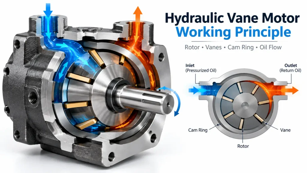
A hydraulic vane motor converts hydraulic power into rotation using a slotted rotor, sliding vanes and an offset cam ring. Pressurized oil fills the chambers between the vanes, pressure acts on the exposed vane area, and the resulting tangential force turns the rotor and its output shaft. Flow rate sets the shaft speed, and the pressure differential across the motor sets the torque.
The sections below follow that energy path, then cover geometry, applications, selection and maintenance.
What Is a Hydraulic Vane Motor?
A hydraulic vane motor is a positive-displacement rotary actuator: it sweeps a defined volume of oil per revolution and develops shaft torque from the pressure difference between its inlet and its outlet. It is classed as a motor rather than a pump because its job is to produce rotation from fluid power, not to produce flow from rotation.
Positive displacement makes the arithmetic predictable: a fixed swept volume per revolution means speed is set by the flow supplied and torque develops in proportion to the pressure differential. As with any hydraulic motor, it converts rather than generates: flow and pressure in, rotary power out. Manufacturers supply hydraulic vane motors in different displacements, mounting configurations and pressure ratings to match specific machine requirements, from a fixed displacement hydraulic vane motor to variable versions.
Inside a Hydraulic Vane Motor: Components and Their Jobs
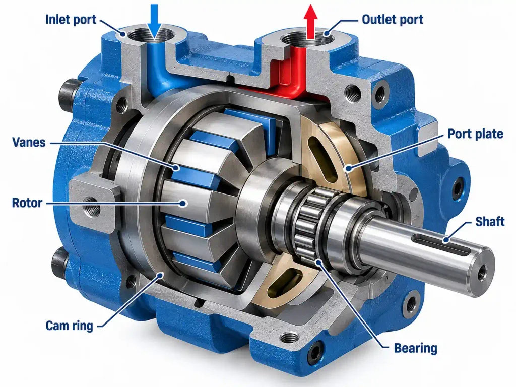
Each part carries a distinct duty, and the table lists the consequences of wear or incorrect fitting.
| Component | Function | Effect of Wear or Incorrect Fit |
| Rotor | Carries the vanes in radial slots and transmits torque to the shaft | Slot wear lets the vanes tilt and leak |
| Vanes | Seal against the cam ring to form the moving chambers | Worn tips leak, so torque and speed fall under load |
| Cam ring | Provides the eccentric working path that defines displacement | Scuffing changes sealing and raises noise and heat |
| Port plates | Direct oil into and out of each chamber and set the timing | Scoring causes cross-port leakage and local overheating |
| Shaft, bearings and seals | Transmit torque, carry external loads and contain leakage | Misalignment, overhung load or high case pressure shorten life |
Balanced vs Unbalanced Vane Motors: Radial Load Differences
A single-lobe cam ring creates one pressure zone, so the rotor is pushed to one side through the whole revolution and the bearings carry that load. A double-lobe cam ring creates two opposed pressure zones, so radial forces largely cancel and higher working pressures become practical.
How Does a Hydraulic Vane Motor Work Step by Step?
Oil enters the inlet port and fills the space between two adjacent vanes. Because the cam ring is offset from the rotor centre, chamber volume grows on the inlet side and shrinks on the outlet side. Pressure on the exposed vane faces produces a tangential force that rotates the rotor, and the oil leaves through the outlet port.
Each vane pair follows the same sequence; the steps below trace one chamber from inlet to outlet.
The Working Cycle From Inlet Port to Outlet Port
- Pressurized oil enters the inlet port and fills the space between two adjacent vanes.
- The vanes are held out against the cam ring, so each vane pair closes a working chamber.
- Chamber volume grows along the rising part of the ring, drawing oil in at inlet pressure.
- Pressure acts on the exposed area of each vane, producing a force tangential to the rotor.
- Chamber volume shrinks along the falling part of the ring, pushing oil out the outlet port.
- The resulting torque turns the rotor and its output shaft.
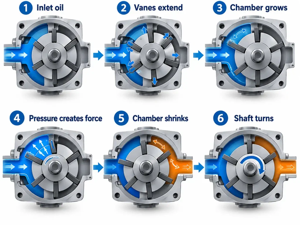
How Pressure on the Vanes Creates Shaft Torque
Think of each extended vane as a small piston pushing sideways against the rotor. Torque comes from the difference between inlet and outlet pressure acting on the exposed vane area, not from pressure alone. A larger exposed area or pressure differential gives a greater turning force acting at a radius, so torque rises with both. If return-line pressure rises, the useful differential falls and torque falls with it. In a production hydraulic vane motor, this is managed through port plate geometry, vane design and drain routing rather than by raising supply pressure.
How Vanes Maintain Contact With the Cam Ring
A vane only works while its tip is sealed against the cam ring, so keeping the vanes extended is a design problem in itself. Springs or pressure fed to the vane roots push the vane outward, and once the rotor turns, centrifugal force adds to it. At low speed and during starting, that centrifugal push is weak, so motors that must produce torque from standstill rely on spring or pressure-fed extension. The mechanism matches the one used in a rotary vane pump, but a pump is driven from outside and tolerates weak vane contact at low speed, while a motor must develop torque at any speed the load demands.
Vane Geometry, Displacement and Torque-Speed Relationship
Cam ring geometry sets how much oil the motor sweeps in one revolution, and that swept volume, called displacement, links flow to speed and pressure differential to torque. Displacement is fixed in most vane motors, so flow sets speed and pressure differential sets torque.
Because the geometry is fixed in the cam ring, a given motor demands the same flow for a given speed, so the duty point has to be right from the start.
How Cam Ring Geometry Controls Displacement
In simple terms, displacement is how much oil the motor converts into rotation in each revolution, so it sets the balance between torque and speed. Technically, it rises with the eccentricity between rotor centre and ring centre, with vane width and with the number of lobes, and greater eccentricity raises both swept volume per revolution and radial bearing load.
| Cam Ring Configuration | Rotor Loading | Practical Consequence |
| Single lobe with one pressure zone | Rotor pushed to one side throughout the revolution | Simple porting, lower pressure ceiling, heavier bearing duty |
| Double lobe with two opposed pressure zones | Radial forces largely cancel | Higher pressure capability, two inlet and two outlet zones, more complex porting |
| Shifting ring for variable displacement | Load changes as the ring moves | Displacement can be trimmed for speed or torque, with added control hardware |
Torque and Speed Explained Simply
Put simply, more pressure difference means more torque and more flow means more speed. Numerically, output torque is the pressure differential multiplied by displacement, divided by two pi, then reduced by mechanical efficiency, and shaft speed is the flow rate divided by displacement, then reduced by volumetric efficiency. Both are approximations until the manufacturer’s performance curves are applied, since leakage, friction and viscosity separate the ideal figure from the catalogue figure. These relationships are not unique to vane designs; the wider picture is covered in How Does a Hydraulic Motor Work.
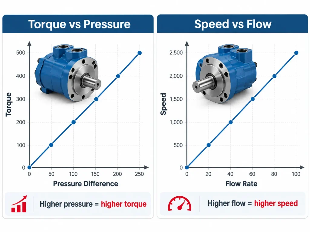
Fixed and Variable Displacement Vane Motors
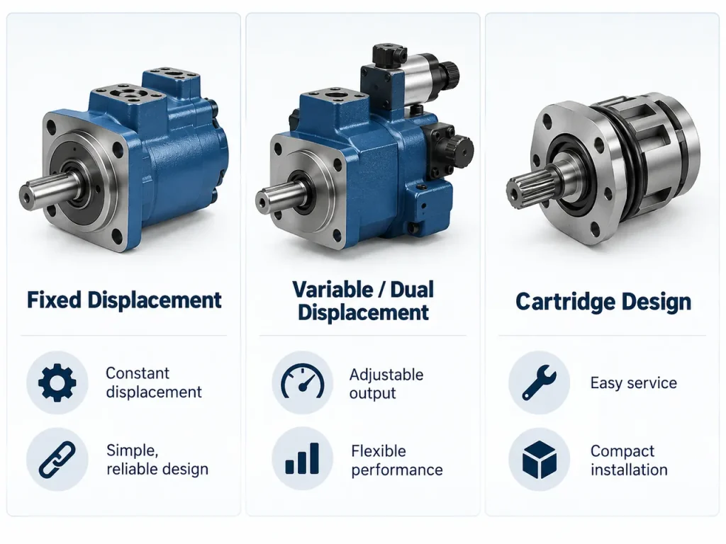
A fixed-displacement motor sweeps one volume per revolution, so speed changes only with the flow supplied to it. That suits drives fed by a variable pump at a roughly constant operating point. Where displacement can be shifted, the motor can be set for higher torque at lower speed or the reverse, but the shift changes flow demand as well as output, so pump and circuit must be reviewed together. Many variable vane designs offer two positions rather than continuous control.
Hydraulic Vane Motor vs Vane Pump: Key Design Differences
A vane motor and a vane pump share the same working geometry but are designed against opposite priorities. A pump is turned by a shaft and must draw oil into its chambers; a motor is driven by oil pressure and must produce torque at whatever speed the load demands. The difference shows up in vane retention, port timing, drain arrangement and bearing sizing.
In a pump, the vanes can rely on centrifugal force once it is up to speed, because the shaft is already turned by external power. In a motor, torque is needed from standstill, so vane contact must be assured before rotation begins. Port timing follows the same logic: a pump must open its inlet port early enough to fill without cavitation, while a motor must admit pressure where the vanes convert it into torque. Suction, priming and cavitation are pump-side concerns, and a motor has no suction requirement of its own, so self-priming belongs to pump selection, covered in How Does a Vane Pump Work.
Where Hydraulic Vane Motors Are Used
Vane motors are selected for drives that need smooth, continuous rotation at moderate pressure with generous flow, in a compact body with low torque ripple. They are seldom chosen for the highest pressure or the highest efficiency, and not for every drive of that kind.
Typical duties include:
- Cooling fan and radiator fan drives on mobile equipment
- Screw and injection units on plastics and die casting machinery
- Mixers, agitators and shredders
- Conveyor and material handling drives
- Marine and shipboard auxiliary equipment
The list shows where the technology fits best, not where it is used exclusively. In construction machinery, swing and travel drives often use axial piston motors with a gearbox, so each duty needs its own check. A suspended load is held by a brake or a load-holding valve, not by the motor. Fan drives are a common home for these motors, and the wider component range is gathered under hydraulic parts for construction industry.
Advantages and Limitations of Hydraulic Vane Motors
The strengths of a vane motor are smooth output, low torque ripple, compact power density, good starting torque and quiet running. The limits are sensitivity to contamination and viscosity, dependence on correct drain and back pressure, and efficiency below that of a high-pressure piston motor.
The strengths show up in the driven machinery:
- Low torque ripple, so shafts, couplings and driven equipment see fewer torsional shocks
- Good starting torque for the envelope, which helps drives that begin under load
- Reversible operation in designs built for it
The limits follow from the same geometry and are mostly manageable:
- Contaminated or incorrect-viscosity oil opens clearances and costs both torque and speed
- Vane tips and the cam ring surface are the parts most exposed to abrasives
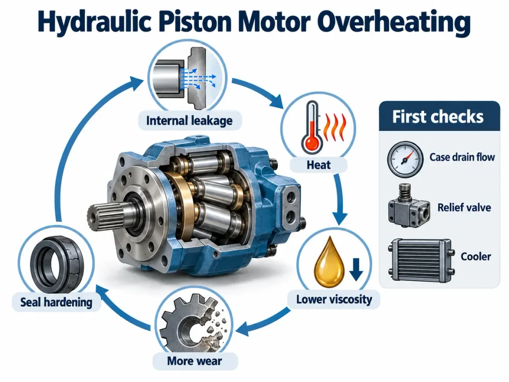
- Case drain and back pressure limits have to be respected or the shaft seal suffers
- Very low running speeds need checking, because vane contact and film thickness fall
- Pressure spikes can damage port plates, vanes and the cam ring before a gauge registers them
How to Select and Maintain a Hydraulic Vane Motor
Selection starts from the load rather than from a part number. The duty defines the torque needed at starting, running and stall, the pressure differential the circuit can maintain, and the flow available to reach the target speed. Displacement follows from those numbers.
Only once the duty is defined should catalogue options be compared, and the comparison should end with the manufacturer’s performance curves rather than ideal formulas.
Selection Checklist
- Establish the torque required at starting, running and stall conditions.
- Confirm the pressure differential the circuit can hold across the motor.
- Calculate the displacement needed to develop that torque.
- Check the target speed against the flow the pump can deliver.
- Verify continuous and intermittent pressure ratings for the actual duty cycle.
- Confirm drain arrangement, permissible drain pressure and return-line conditions.
- Check shaft, flange, port and mounting standards, plus allowable radial and axial load.
- Review fluid type, viscosity range, filtration level and operating temperature.
If a standard vane motor cannot meet the torque, mounting or operating requirements, a custom hydraulic motor can be specified around the machine instead of being adapted to it.
When to Choose a Vane Motor Instead of a Piston Motor
A vane motor is generally the better fit at moderate pressure with generous flow, when smooth continuous rotation matters and compact size and quiet running outweigh peak efficiency. A piston motor becomes the better fit as pressure and efficiency requirements rise, or when duty is highly intermittent with high peak loads and precise control is needed. On many machines the two are not alternatives at all, with a piston motor driving the main function and a vane motor handling an auxiliary circuit.
Installation and Maintenance Notes
Keep the oil clean, dry and within the recommended viscosity range, and change filters before bypass operation becomes routine. Verify coupling alignment and shaft loading, since misalignment and high radial load cause many bearing and seal failures. When replacing a motor, do not treat two units as interchangeable because displacement matches: confirm pressure rating, shaft load capacity, drain configuration, mounting standard, port orientation and rotation. General installation and safety practice is set out in ISO 4413.
FAQ
Can a hydraulic vane motor run smoothly at very low speed?
Smoothness depends on vane contact and on how steady the flow is. As speed falls, the oil film and centrifugal assistance weaken, so most designs have a practical minimum speed. Where a drive must creep under load, a radial piston motor or gearbox is more predictable.
What limits the maximum speed of a hydraulic vane motor?
Maximum speed is limited by vane friction and wear, by how completely the inlet chambers fill, and by the pressure drop needed to push oil in. Beyond a point the chambers cannot fill in time and output falls away, so rated speeds come from test data at a stated viscosity.
Does a vane motor need a case drain?
Many vane motor designs use a case drain, which carries leakage away from the shaft seal and keeps the pressure behind it within limits. Whether a unit needs one depends on the design and return-line pressure, and the permissible drain pressure is a selection parameter.
What is the difference between a vane motor and a gear motor?
A gear motor drives the shaft through meshing gears, which makes it simple, tolerant of contamination and usually cheaper. A vane motor uses a rotor and cam ring, giving smoother output, lower torque ripple and a more compact body for the same duty. The choice turns on whether smoothness outweighs the lowest purchase cost.
Are hydraulic vane motors reversible?
Many are, but reversibility is a design feature rather than a property of every vane motor. Bidirectional units use symmetrical porting and arrange the drain so the shaft seal does not face full pressure in either direction. Single-direction designs may rely on asymmetric port timing, so state the requirement when specifying.