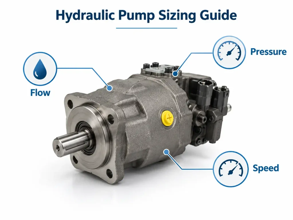
Industrial hydraulic and fluid-transfer systems often need a compact pump that can produce steady flow without excessive noise or pulsation. A vane pump meets these requirements by using sliding vanes to create controlled pumping chambers inside a rotating assembly.
A vane pump is a rotary positive displacement pump in which vanes mounted in a slotted rotor move against a cam ring or housing. As the rotor turns, the chambers between the vanes expand to draw in fluid and then contract to discharge it. Vane pumps are commonly used to circulate hydraulic oil, transfer lubricating liquids, and supply predictable flow to industrial equipment.
Understanding its operating principle, construction, limitations, and fluid requirements is essential when determining whether a vane pump is suitable for a particular system.
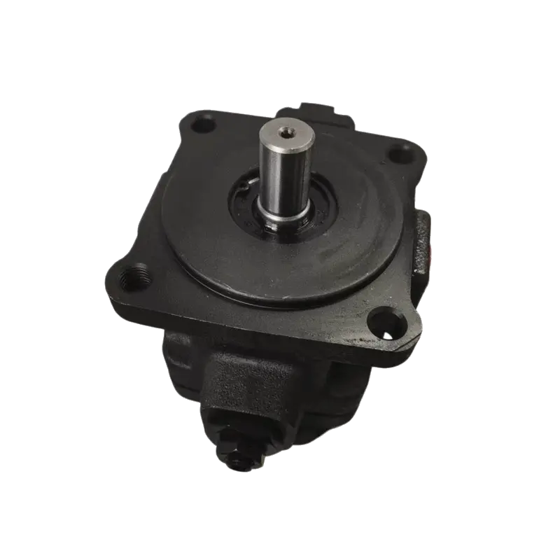
What Is a Vane Pump and What Is Its Purpose?
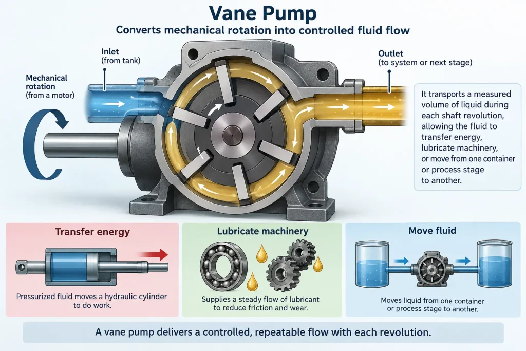
The purpose of a vane pump is to convert mechanical rotation into controlled fluid flow. It transports a measured volume of liquid during each shaft revolution, allowing the fluid to transfer energy, lubricate machinery, or move from one container or process stage to another.
A typical vane pump contains a rotor positioned inside a cam ring or specially shaped housing. Radial slots in the rotor hold movable vanes. These vanes extend toward the surrounding surface and divide the space between the rotor and housing into separate chambers.
Because it is a positive displacement pump, its theoretical flow is determined primarily by displacement and rotational speed. Actual output is slightly lower due to internal leakage and changes in fluid viscosity, pressure, wear, and operating clearances.
The term vane pump most often refers to a liquid-handling or hydraulic pump. Rotary vane vacuum pumps use a related chamber-changing principle to remove gases, but their construction, lubrication requirements, performance measurements, and applications may differ substantially.
How Does a Vane Pump Work?
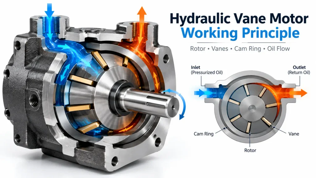
A vane pump works by repeatedly increasing and decreasing the volume of sealed chambers formed between adjacent vanes, the rotor, side plates, and cam ring. Expanding chambers draw fluid through the inlet, while contracting chambers force it through the outlet.
The operating cycle can be divided into four stages:
- Rotation: An electric motor, engine, or other prime mover turns the pump shaft and rotor.
- Intake: Where the distance between the rotor and cam surface increases, the spaces between adjacent vanes become larger. The resulting pressure reduction allows fluid to enter through the inlet.
- Transfer: The rotating vanes trap fluid in individual chambers and carry it around the pump body. Close internal clearances limit reverse leakage.
- Discharge: As the rotor approaches the outlet region, the available chamber volume decreases, raising the pressure and forcing the trapped fluid out through the discharge port as the vanes retract into their slots.
The pump produces flow rather than independently determining system pressure. Pressure develops when the downstream circuit resists that flow. The pump, drive, piping, valves, and relief devices must therefore be designed for the expected operating load.
How the Vanes Maintain Contact
Vane tips must remain close to the cam surface to preserve the pumping chambers. Depending on the design, outward contact may be maintained by centrifugal force, springs, hydraulic pressure, or pressure-loaded pins.
At low starting speeds, centrifugal force alone may be insufficient. Mechanically or hydraulically assisted designs can maintain contact more reliably during start-up and low-speed operation. The correct priming procedure remains important because it ensures the pump is filled with fluid, which frequently provides the internal lubrication and cooling needed to prevent dry running.
What Are the Main Components of a Vane Pump?
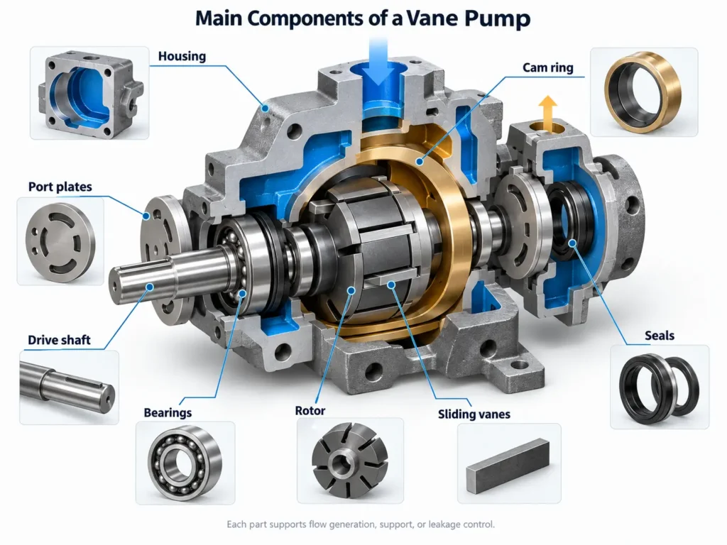
The main components of a vane pump are the drive shaft, rotor, sliding vanes, cam ring, port or side plates, housing, bearings, and seals. Each component contributes to chamber formation, fluid distribution, mechanical support, or leakage control.
| Component | Primary function | Effect of damage or wear |
|---|---|---|
| Drive shaft | Transfers torque from the prime mover | Irregular rotation, vibration, or complete loss of pumping |
| Rotor | Holds the vane slots and rotates the pumping group | Excessive clearance, poor flow, or internal damage |
| Vanes | Form moving chamber boundaries and displace fluid | Low output, noise, leakage, or scoring |
| Cam ring | Guides vane movement and controls chamber volume | Reduced efficiency and uneven vane wear |
| Port plate | Directs fluid between inlet and outlet regions | Internal leakage or failure to build pressure |
| Housing | Contains the pumping assembly and fluid passages | External leakage or alignment problems |
| Bearings | Support the shaft and rotating components | Noise, heat, vibration, or shaft movement |
| Seals | Prevent fluid from escaping along joints and the shaft | Visible leakage, air entry, or contamination |
| Relief device | Protects suitable systems from excessive pressure | Overloading or potential component failure if absent or incorrectly set |
Rotor, Shaft, and Vanes
The shaft drives the rotor, while the radial rotor slots allow the vanes to slide inward and outward. A useful characteristic of this arrangement is its ability to compensate for moderate vane-tip wear: the vanes can extend farther from their slots to continue following the cam surface.
This self-adjusting action does not eliminate maintenance. Contamination, inadequate lubrication, incorrect clearances, or severe scoring can prevent free vane movement and cause a rapid decline in performance.
Cam Ring and Port Plates
The geometry of the cam ring determines how chamber volume changes during rotation. Port plates expose the chambers to the inlet and outlet at the correct positions. Their surfaces require accurate tolerances because excessive clearance increases internal leakage, while insufficient lubrication can lead to friction and seizure.
What Types of Vane Pumps Are Available?
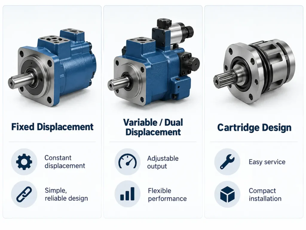
Vane pumps can be classified by hydraulic balance and by displacement control. The principal configurations are unbalanced and balanced vane pumps, while either fixed- or variable-displacement features may be used where the construction permits.
| Configuration | Main characteristic | Primary benefit | Main consideration |
|---|---|---|---|
| Unbalanced | Pumping pressure acts mainly on one side of the rotor | Simple construction and potential displacement adjustment | Higher radial load on the shaft and bearings |
| Balanced | Opposed inlet and outlet regions create counteracting forces | Lower net radial load, reduced vibration, and longer bearing life | Commonly associated with fixed displacement |
| Fixed displacement | Nominal volume per revolution remains constant | Predictable flow and straightforward control | Excess flow may need to be bypassed |
| Variable displacement | Cam-ring position or eccentricity can change | Flow can respond to system demand | More complex controls and adjustment |
Unbalanced Vane Pumps
An unbalanced vane pump normally uses a circular cam ring with the rotor mounted eccentrically. Chamber expansion occurs on the inlet side, while chamber contraction occurs on the outlet side.
Because discharge pressure acts predominantly on one side, the rotor, shaft, and bearings experience a net radial load. This limits some pressure and service-life characteristics but enables relatively simple construction. An unbalanced arrangement may be fixed or variable displacement.
Balanced Vane Pumps
A balanced vane pump typically uses a double-lobed or elliptical cam ring with two opposed inlet regions and two opposed outlet regions. The resulting hydraulic forces largely counteract one another, reducing net radial loading.
Lower radial load can improve bearing life and operating stability. An academic hydraulic systems reference also notes that balancing can reduce operating sound and vibration.
Fixed- and Variable-Displacement Designs
A fixed-displacement vane pump moves a nominally fixed volume during each revolution. Flow is therefore approximately proportional to speed, after accounting for leakage and efficiency losses.
A variable-displacement pump changes the eccentricity between the rotor and control ring. Reducing eccentricity makes the pumping chambers smaller and decreases output. This allows the pump to match changing demand more efficiently than continuously producing excess flow and bypassing it through a valve.
What Are the Advantages and Downsides of Vane Pumps?
Vane pumps offer smooth flow, relatively quiet operation, compact construction, and good efficiency, but they depend heavily on clean fluid, correct lubrication, suitable viscosity, and controlled inlet conditions.
| Advantages | Downsides |
|---|---|
| Smooth flow with relatively low pulsation | Particles can damage vanes, slots, and precision surfaces |
| Lower noise than many comparable pump arrangements | Poor inlet conditions can cause aeration or cavitation |
| Compact size relative to flow capacity | Dry running can remove essential lubrication and cooling |
| Automatic compensation for moderate vane-tip wear | Very high pressures may require a different pump design |
| Fixed- and variable-displacement options | Incorrect viscosity can increase leakage or inlet losses |
| Good performance with many clean, lubricating liquids | Internal precision makes repair quality important |
Low pulsation benefits machine tools, indoor power units, and other systems where vibration and sound must be controlled. A compact pumping group also simplifies equipment packaging.
The major tradeoff is sensitivity to operating conditions. Abrasive particles can score the cam ring and side plates or cause vanes to stick in their slots. Low-viscosity fluid may increase internal leakage, while excessively high viscosity can restrict inlet flow and delay vane movement. Fluid chemistry must also be compatible with the vane material, seals, and housing.
Where Are Vane Pumps Commonly Used?
Vane pumps are commonly applied where clean liquid, moderate-to-high flow consistency, compact size, and low-noise operation are required, and where the fluid is free of abrasive solids and pressures are not extreme.
Industrial Hydraulic Systems
Typical industrial applications include hydraulic power units, machine tools, presses, clamping equipment, material-handling machinery, and lubrication circuits. Smooth delivery helps actuators move consistently, while variable-displacement versions can reduce wasted flow in systems with changing demand.
Mobile and Transportation Equipment
Vane pumps may support steering, lifting, transmission, lubrication, or auxiliary hydraulic functions in mobile machinery and transportation equipment. Liquid-transfer versions can also load or unload tanks containing compatible fuels, oils, and other lubricating fluids.
Process and Fluid-Transfer Systems
Suitable designs can transfer petroleum products, solvents, coatings, edible oils, refrigerants, and other clean liquids. Application approval should never be based on the fluid name alone. Engineers must evaluate viscosity at actual operating temperature, lubricity, vapor pressure, corrosion potential, seal compatibility, solids content, and regulatory requirements.
Some transfer pumps are self-priming or reversible, but these characteristics are design-specific. The technical documentation should confirm allowable suction lift, rotation direction, and reverse-operation capability.
What Are Common Vane Pump Problems?
Common vane pump problems include low flow, failure to build pressure, excessive noise, cavitation, aeration, overheating, external leakage, internal wear, and sticking vanes. Many of these symptoms originate from contaminated fluid, improper viscosity, inadequate priming, or restricted inlet conditions.
| Symptom | Likely causes | Recommended checks |
|---|---|---|
| Low or no flow | Wrong rotation, worn pumping group, blocked inlet, stuck vanes | Verify rotation, inlet condition, fluid level, and internal wear |
| Low pressure | Internal leakage, incorrect valve setting, excessive load | Test actual flow, inspect valves, and compare load with system rating |
| Excessive noise | Aeration, cavitation, misalignment, bearing wear | Check suction connections, fluid level, viscosity, and shaft alignment |
| Overheating | Continuous relief flow, excessive pressure, internal leakage | Check load, valve settings, fluid temperature, and pump condition |
| External leakage | Damaged seal, loose connection, shaft movement | Inspect seals, fittings, bearings, and shaft condition |
| Irregular output | Air in the circuit, contamination, sticking vanes | Bleed the system and inspect fluid cleanliness and vane movement |
Low Flow or Failure to Build Pressure
A pump that cannot produce expected flow may be rotating in the wrong direction, operating too slowly, receiving insufficient fluid, or suffering from excessive internal leakage. Air trapped during installation can also prevent pressure from building normally.
If the pump fails to prime or develop pressure shortly after start-up, it should be stopped before further testing. Continuing to run it can turn a correctable inlet problem into severe internal damage.
Excessive Noise, Cavitation, and Aeration
Cavitation occurs when local pressure falls low enough for vapor cavities to form and collapse. Common causes include restricted suction piping, excessive speed, high fluid viscosity, or inadequate inlet pressure.
Aeration occurs when external air enters the fluid, often through loose suction connections, a low reservoir level, or an unsuitable return-line arrangement. Both conditions can produce noise, erratic output, heat, and surface damage, but their corrective actions differ fundamentally.
Can a Vane Pump Run Dry?
A conventional liquid vane pump should not run dry unless its documentation expressly permits it. The pumped liquid often lubricates the vanes, cam ring, rotor faces, and port plates while also removing heat.
Initial filling, circuit priming, and air bleeding should be completed before the pump operates under load. Published technical start-up instructions warn against starting a vane pump without internal lubrication. Even if a specialized material can tolerate a brief dry start, that capability should not be interpreted as permission for continuous dry running.
What Is the Most Common Cause of Pump Failure?
There is no single cause that applies to every pump and operating environment. For vane pumps, however, contaminated or unsuitable fluid and poor inlet conditions are widely recognized as leading root-cause categories.
Particle contamination accelerates abrasive wear and can restrict vane movement. Water can reduce lubricating performance and promote corrosion. Entrained air weakens the fluid film, while incorrect viscosity can cause either excessive leakage or inadequate inlet flow. Effective filtration, proper reservoir management, correct fluid selection, and careful commissioning therefore help prevent multiple failure modes at once.
How Do You Select the Right Vane Pump?
Selecting a vane pump requires matching its displacement, flow, pressure rating, speed range, materials, and inlet requirements to the actual fluid and duty cycle rather than choosing only by port size or nominal power.
Use the following selection checklist:
- Define the required flow at normal and peak operating conditions.
- Calculate the necessary displacement from flow, speed, and expected volumetric efficiency.
- Confirm continuous and intermittent pressure limits.
- Determine fluid viscosity across the complete temperature range.
- Verify fluid lubricity and compatibility with vanes, seals, and wetted metals.
- Establish the required cleanliness level and filtration arrangement.
- Calculate suction losses and available inlet pressure.
- Review start-up, priming, air-bleeding, and shutdown procedures.
- Evaluate noise limits, duty cycle, service access, and expected maintenance conditions.
- Provide correctly rated pressure protection for the pump and downstream circuit.
A well-selected vane pump can deliver smooth, efficient service for a long operating period. Reliable performance depends on treating the fluid, inlet piping, filtration, controls, and maintenance practices as parts of the complete pumping system.
FAQ
Can a Vane Pump Be Used as a Hydraulic Motor?
Some vane units are specifically designed to operate as hydraulic motors, converting fluid pressure and flow into shaft rotation. A pump should not automatically be used as a motor, however. Internal porting, pressure balance, shaft loading, lubrication, and allowable rotation may differ. Only a unit expressly rated for motor or reversible pump-motor operation should be used this way.
What Is the Difference Between a Vane Cartridge and a Complete Pump?
A vane cartridge is the internal pumping group, usually including the rotor, vanes, cam ring, and associated plates. A complete pump also includes the housing, shaft, bearings, seals, ports, and mounting features. Replaceable cartridges can simplify service, but the surrounding pump and system must be inspected so that contamination, misalignment, or inlet problems do not damage the new assembly.
How Is Theoretical Vane Pump Flow Calculated?
Theoretical flow is calculated by multiplying displacement per revolution by shaft speed. For example, a pump with a displacement of 20 cubic centimeters per revolution operating at 1,500 revolutions per minute has a theoretical flow of 30 liters per minute. Actual flow will be lower because of internal leakage, which increases with wear, pressure, temperature, and reduced fluid viscosity.